22 minute read
SAFETY

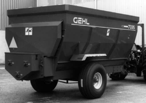
from Gehl Mixer Feeders 7000 Series MF7210 MF7285 MF7335 MF7435 MF7500 Operators Manual 907060A - PDF

NEVER use your hands to search for hydraulic fluid leaks, use a piece of paper or cardboard. Escaping fluid under pressure can be invisible and can penetrate the skin and cause a serious injury. If any fluid is injected into your skin, see a doctor at once. Injected fluid MUST be surgically removed by a doctor familiar with this type of injury or gangrene may result.
ALWAYS follow state and local regulations regarding use of a safety chain and transport lighting when towing farm equipment on public highways. Restrict highway towing speeds to 20 mph (32 kmh) maximum. BE SURE to check with local law enforcement agencies for your own particular regulations. Unless otherwise prohibited, use a Slow-moving Vehicle Emblem.
Only a safety chain (NOT an elastic or nylon/plastic tow strap) should be used to retain the connection between the towing and towed machines, in the event of separation of the primary attaching system.
Good safety practice dictates that you NEVER tow an implement (without brakes) unless the towing vehicle weighs at least one-and-one half (1-1/2) times the weight of the towed implement and its load. For any public highway travel and to be in compliance with this rule, BE SURE that your tractor is heavy enough to counterbalance the weight of the Mixer Feeder.
To ensure continued safe operation, replace damaged or worn-out parts with genuine GEHL service parts, BEFORE attempting to operate this equipment.
Our Company does NOT sell replacement tires. In addition, tire mounting, service or inflation can be dangerous. Whenever possible, trained personnel should be called to service and/or mount tires, following the tire manufacturer’s instruction. If you do NOT have such instructions, contact your tire dealer or our Company. In any event, to avoid possible fatal or serious injury, follow the specific directive given in the Service chapter of this manual.
To avoid injury, stay out of the Mixer Feeder Box. If entrance into the Mixer Feeder Box is required, BE SURE to exercise the MANDATORY SAFETY SHUTDOWN PROCEDURE BEFORE going in.
REMEMBER, it is the owner’s responsibility for communicating information on the safe use and proper maintenance of this machine.
CHAPTER 5 CONTROLS & SAFETY EQUIPMENT
MF7000 Series Mixer Feeders are provided with numerous features for operator safety and convenience.
Caution
Become familiar with and know how to use ALL safety devices and controls on this machine BEFORE attempting to operate the unit. Know how to stop machine operation BEFORE starting it.
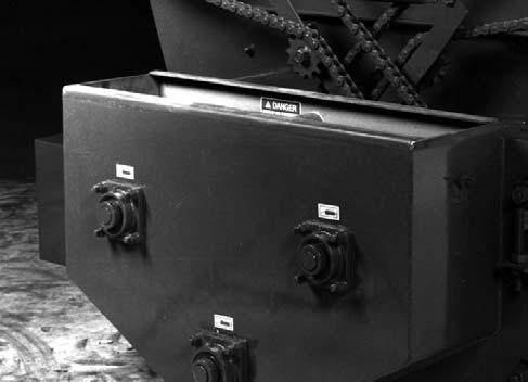
DRAIN
The Mixer Feeder is provided with a Drain Plug in the bottom of both Auger Troughs at the front of the unit. BE SURE that the Plugs are in place BEFORE loading the Mixer Feeder.
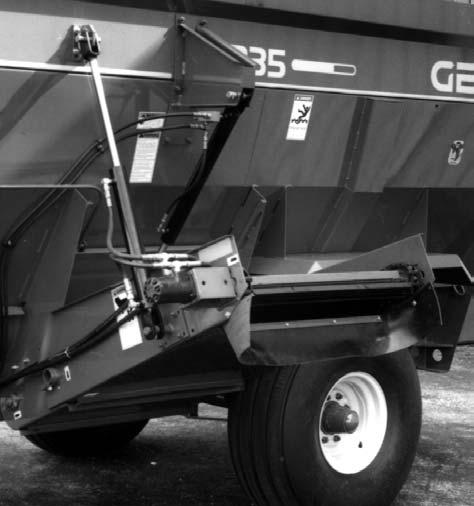
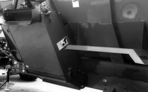
Discharge Conveyors
One-Piece Conveyor (Fig. 2)
Trailer or Truck-mounted GEHL Mixer Feeders are available with a One-piece Discharge Conveyor. When installed, the Conveyor can be attached in either a 30° or a 40° position. A Hydraulic Motor is used to directly drive the Conveyor Apron. Material is discharged whenever the Hydraulic Motor is operated with the tractor or truck remote-controlled hydraulics system.

Caution
The Discharge Conveyor Apron operates whenever the remote hydraulics control is activated.
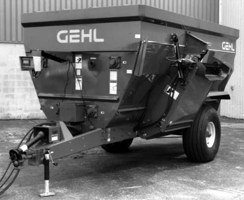
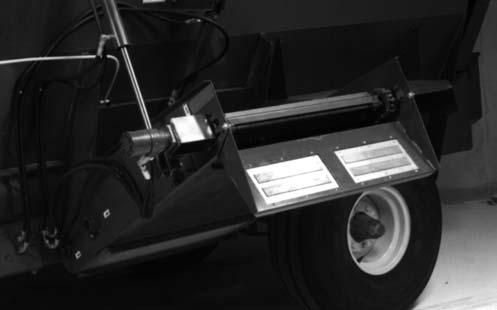
Two-Piece Conveyor (Fig. 3)
Trailer or Truck-mounted GEHL Mixer Feeders are available with a Two-piece Discharge Conveyor. The Conveyor is designed to be pivoted from the ”transport” to the ”operating” position, and back to “transport”, by a remotely-controlled Hydraulic Cylinder. A Hydraulic
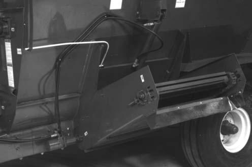
Motor is used to directly drive the Conveyor Apron. When the Hydraulic Cylinder extends the Conveyor to the “operating” position, the Hydraulic Motor automatically starts to run the Conveyor Apron and discharge material. Hydraulic Motor operation is stopped whenever the hydraulic control lever is placed in neutral position or Hydraulic Cylinder is retracted to move the Discharge Conveyor to the “transport” position.
Warning
The Discharge Conveyor will automatically begin to operate after the Conveyor Control Cylinder reaches the end of its extension stroke, as long as the tractor remote hydraulics control lever is activated. Keep hands out. Do NOT step or climb over unit while machine is operating. The Rotating Conveyor can crush and dismember. Failure to heed could result in death or serious injury.
Accessory Discharge Conveyor
As a safeguard for livestock, a Magnet can be installed into the end of either the One-Piece or the Two-Piece Discharge Conveyor. The Magnet will extract harmful metal debris before it drops into the feeder bunk.
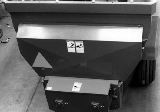
DISCHARGE
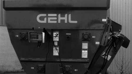
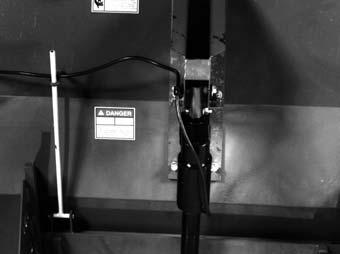
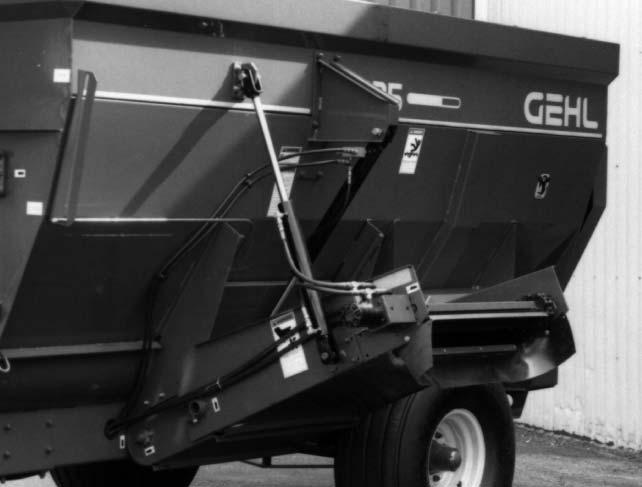
Door
CONTROL & INDICATOR (See Fig. 3)
Trailer-Mounted and Truck-Mounted Mixer Feeders are furnished with a Hydraulic Cylinder and StationaryMounted Mixer Feeders are furnished with a 110 V A.C. voltage powered Linear Actuator to remotely regulate the position of the Discharge Door. A Position Indicator is provided for visual monitoring of the amount of Door opening.
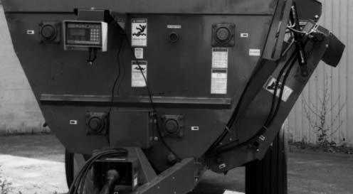
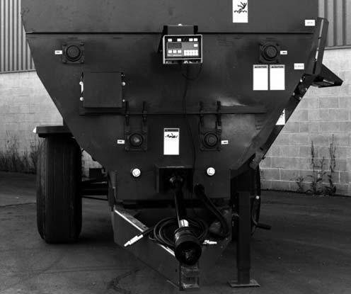
Electronic
All Mixer Feeder models are furnished with Electronic Weigh Scales as standard equipment, to facilitate accurate weight measurement for feed rationing. The 7210, 7285 and 7335 Trailer-Mounted models use a 3-point Weighbar system and the 7435 and 7500 Trailer models use a 4-point Weighbar system. All Mixer Feeder models use a 4-point Weighbar system for Truck-Mounted or Stationary applications. The MF7210 is available as a Stationary unit but NOT for Truck Mounting. For additional details, refer to information packaged with the Weigh Scale system.
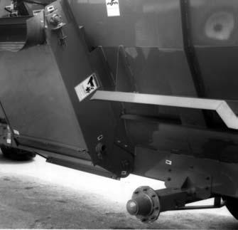
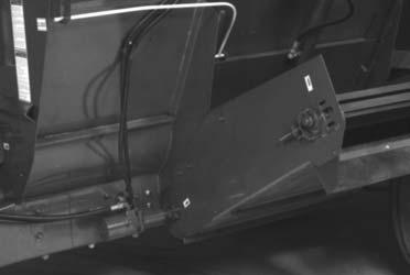
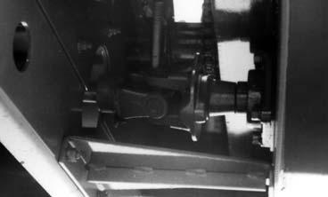
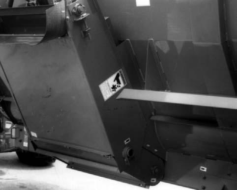
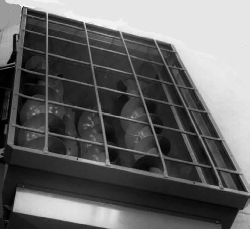
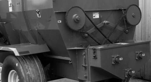
GUARDS & SHIELDS (Figs. 6 & 7 & see Fig. 1)
Whenever possible and without affecting machine operation, Guards and Shields have been used on this equipment to protect potentially hazardous areas. In specific places, Decals are also provided to warn of potential dangers as well as to display special operating procedures. The drive components of the Mixer Feeder are protected by a large Rear Shield which is attached by two alignment Studs at the bottom and Bolts in the upper corners. On Trailer units, the Drive Input connection is covered by two separate bolted-on Shields and the Telescoping PTO Drive connection to the tractor is equipped with rotating Shields. Stationary units are provided with Drive Belt and Discharge opening Guards. In addition, the top of the Stationary Mixer Feeder Tank is furnished with a repositionable Steel Bar Grate.
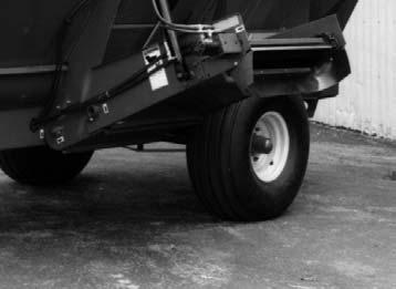
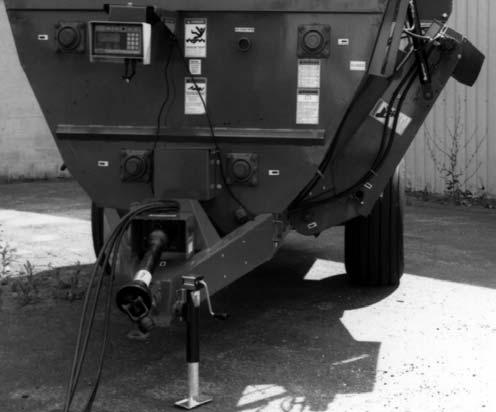
HITCHJACK (See Fig. 1) WARNING
BE SURE the Locking Pin is properly seated into the holes thru the Jack Tube and the Hub on the Mixer Feeder Drawbar BEFORE the tractor is disconnected.
A Hitchjack is furnished with a Trailer-type Mixer Feeder to support the machine when the tractor is disconnected as well as to facilitate aligning the Hitch Clevis with the tractor drawbar for hookup.
When the Jack is NOT being used to support the Mixer Feeder, it can be relocated to the ”storage” Hub provided on the front of the unit.
Hydraulic Systems
Caution
BEFORE proceeding to perform any work on the unit and BEFORE removing or opening any Shields or Covers, BE SURE to exercise the MANDATORY SAFETY SHUTDOWN PROCEDURE (page 8). BE SURE to replace ALL Shields and Covers BEFORE resuming operation.
GEHL Mixer Feeders are available with appropriate hydraulic systems to match the requirements of the Discharge Conveyor installed, the type of mountings (Truck or Trailer) and (for Trailer Units only), the available remote hydraulic control circuit(s) of the tractor.
Standard Hydraulics Package
The Standard Hydraulics packages are designed to be used to operate Trailer-type Mixer Feeders with tractors having two separate remote hydraulics circuits. All of the packages, which essentially differ by their Hose and Tubing lengths to fit the different size units,provide Hoses, Tubes and Fittings to interconnect the Door
Control Cylinder to one pair of remote tractor outlets. The Conveyor Apron Drive Motor (for a One-Piece Discharge Conveyor) or the Conveyor Apron Drive Motor and the parallel-connected Conveyor Control Cylinder (for a Two-Piece Discharge Conveyor) are likewise interconnected to a second pair of remote tractor outlets.
Single Valve Conversion Package
The Standard Hydraulics packages, described under the previous subtopic, are designed for operation by a tractor with two separate remote hydraulic circuits. The Single Valve Conversion package is designed to adapt the Mixer Feeder Control Cylinder(s) and the Conveyor Drive Motor for operation by a tractor with only one remote hydraulic circuit.
Self-contained Hydraulics Systems
The Self-contained Hydraulics Systems are designed for Truck-mounted (and optional Trailer-type) applications. The systems consist of a Hydraulic Pump, Reservoir, Filter, Directional Flow Control Valves and appropriate Hoses, Tubes and Fittings to adapt to the various model Mixer Feeders (except the 7210 model).
1000 RPM (FIELD) CONVERSION KIT
All Trailer-type Mixer Feeders (except the 7210 model) can be field-converted for operation by a 1000 PTO RPM tractor. Conversion involves exchange of the Telescoping PTO Drive and Sprocket changes, inside the Chain Case.
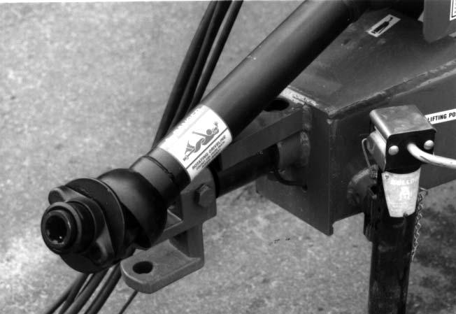
SAFETY CHAINS & TRANSPORT LIGHTING (Fig. 8)
As required or when desired, the Trailer-type Mixer Feeder should be equipped with the appropriate-sized Safety Chain and Transport Lighting for transporting the unit on a public highway. The Chain should be routed as shown in the illustration. Refer to the Optional Features & Accessories chapter of this manual for additional ordering information
1 – Safety Chain Fastened to Mixer Feeder Drawbar
2 – Locking Hitchpin
3 – Safety Chain & Clevis
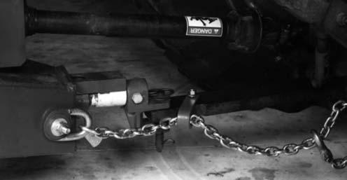
Fig. 8
Caution
ALWAYS follow state and local regulations regarding a safety chain and auxiliary lighting when towing farm equipment on a public highway. BE SURE to check with local law enforcement agencies for your own particular regulations. Only a safety chain (NOT an elastic or nylon/plastic tow strap) should be used to retain the connection between the towing and towed machines, in the event of separation of the primary attaching system.
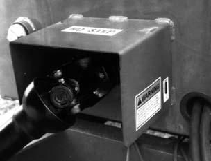
TELESCOPING PTO DRIVE (See Fig. 1) WARNING
On Trailer-type Feeders, BE SURE that the Telescoping Drive Rotates freely inside the Drive Shields Tubes at all times.
The Telescoping PTO Drive is designed to rotate freely inside the Drive Shield Tubes. The Telescoping PTO Drive is provided with a Spring-loaded Locking Device on one end to positively lock the Drive connection onto the tractor PTO shaft. Depress the Locking Device, against the Spring tension, and slide the Yoke onto the tractor PTO Shaft. Release the Locking Device and move the Yoke ahead or back until the Lock engages into the groove of the tractor PTO Shaft.
Danger
Death can result from entanglement. Keep people and clothing well clear. Do NOT operate a Trailer-type Mixer Feeder without: Drive Line Guards, Input Shaft Guards, Tractor Master Shield, and U-Joint locked to tractor and implement shafts.
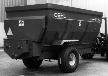
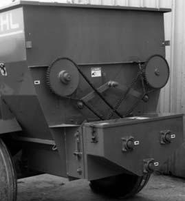
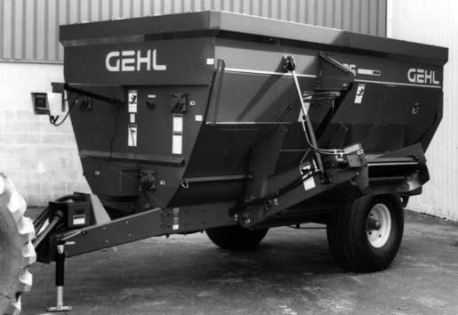
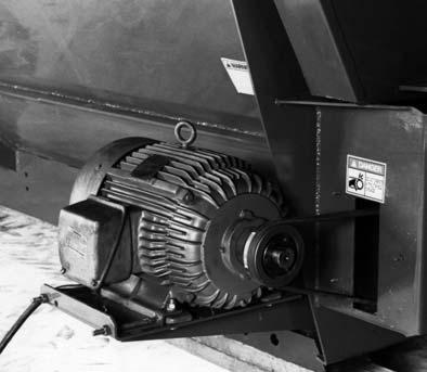
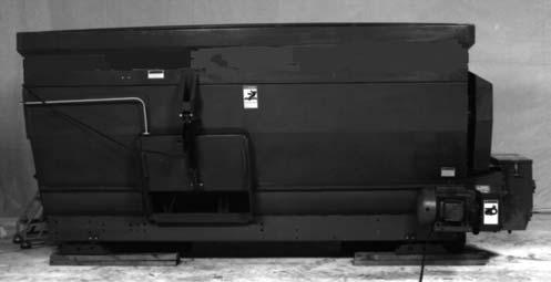
STATIONARY MIXER FEEDERS (Fig. 9)
All GEHL Mixer Feeders are available for Stationary applications. Normally, these units are installed inside a building with electrically-powered conveyor systems to bring material into and carry mixed material away from the unit. Stationary units are equipped with an electric motor-powered Drive and electric Linear Actuator-controlled Discharge Door.
NOTE: For special design, application, installation and operation details, refer to the separate GEHL Stationary Mixer Feeder Supplement, Form No. 907061; ordered separately.
Warning
Stationary Mixer Feeder unit installations MUST comply with all rules and guidelines set forth in ASAE Standard S354.2. Of major importance, BE SURE to install and wire all electrically powered devices in accordance with ALL applicable national, state and local codes regarding shielding, overload protection and positive electric power source lockouts.
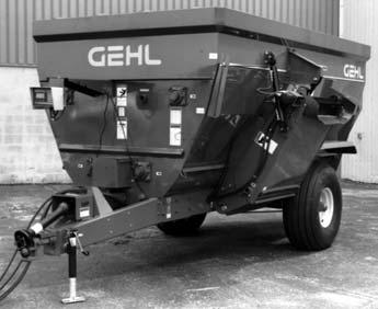
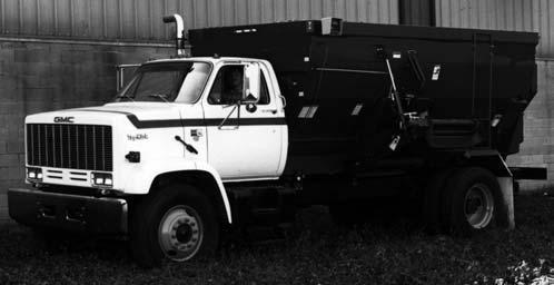
TRUCK-MOUNTED MIXER FEEDERS (Fig. 10)
All GEHL Mixer Feeders (with the exception of the 7210 model) are available for Truck-mounted applications. Normally, these units are adapted to an appropriately-sized truck frame on a 4-point Weigh Scale mounting arrangement. The Mixer Feeder Drive Line is powered from a (manufacturer provided) truck Power Take-off (PTO).
NOTE: For special design, application, installation and operation details, refer to the separate GEHL Truck-mounted Mixer Feeder Supplement, Form No. 907062; ordered separately.
Chapter 6 Operation
General Information
GEHL MF7000 Series Mixer Feeders are designed to completely mix, blend and feed livestock rations. Trailer-type and Truck-mounted models are also designed for transporting livestock rations and discharging them directly into a bunk-feeder.
Warning
BEFORE operating the Mixer Feeder, review and comply with ALL applicable recommendations set forth in the SAFETY chapter of this manual.
NOTE: The following information applies specifically to Trailer-type units, unless otherwise noted. Most of this information also applies to Truck-mounted units and some information will also be applicable to Stationary units.
Emergency Shut-down
In an emergency or in case a foreign object becomes lodged in the Discharge Conveyor, Door or Conveyor Augers, STOP Mixer Feeder operation IMMEDIATELY by disengaging the tractor or truck PTO or by shutting-off the electric motor on Stationary units. BE SURE to exercise the MANDATORY SAFETY SHUTDOWN PROCEDURE (page 8) BEFORE proceeding to correct the problem.
Tractor Hook-up (Fig. 11)
Proper operation requires a tractor with sufficient horsepower to run the PTO and size to counterbalance the weight of a loaded Mixer Feeder. Refer to the Specifications chapter for loaded weights and horsepower requirements.
NOTE: By design, this Mixer Feeder can only be properly hooked-up to a tractor which has PTO and hitch dimensions conforming to ASAE Standard S203.
Caution
BE SURE to use a locking hitchpin to make the Mixer Feeder connection to the tractor drawbar.
1 – Tractor PTO Shaft*
2 – 14” (355 mm) for 540 RPM or 16” (405 mm) for 1000 RPM
3 – Sliding Coupler Lock
4 – 6 to 12” (150 to 300 mm) - 8” (203 mm) Standard*
5 – Locking Hitchpin
6 – Tractor Drawbar
* Tractor MUST comply with ASAE Standard S203
Fig. 11
PTO Connection
NOTE: This GEHL Mixer Feeder is designed for standard 540 RPM PTO operation or field-converted 1000 RPM PTO operation; Do NOT attempt to operate unit at higher than the respective rated speeds.
It is very important that a measurement of 14” for 540 RPM units (or 16” for 1000 RPM field-converted units) is established and maintained from the end of the tractor PTO shaft to center of the tractor drawbar pin hole.
Warning
BE SURE that the Telescoping PTO Coupler is properly secured to the tractor PTO shaft. Likewise, BE SURE that the Rotating Shields turn freely BEFORE starting the tractor engine.
Telescoping PTO Drive (All Models)
NOTE: Do NOT attempt to use a hammer to aid in attaching the Drive Coupler to the tractor PTO shaft.
With the correct distance established, slide back the Coupler Lock and attach the PTO Drive to the tractor PTO shaft. Make sure that the Coupler locks onto the PTO shaft; slide it back and forth until it locks. The Telescoping PTO Drive Shaft is designed to only be operated with the Mixer Feeder and tractor in a straight line (or less than 15° from a straight line). Disengage the PTO before maneuvering greater angles.
NOTE: To prevent damage to the Telescoping Drive, NEVER allow the tractor’s rear tires to make contact with the Telescoping Drive while making sharp turns. Be especially careful when pulling the Mixer Feeder with a tractor equipped with a 3-point hitch.
Hydraulics System Controls
The hydraulic controls for operating the Mixer Feeder are different as described under the following subtopics.
Standard Hydraulics Package (Fig. 12)
The Standard Hydraulics package is designed to be used to operate a Trailer-type Mixer Feeder by a tractor having two separate remote hydraulics circuits, as shown in the Schematic Diagram provided. Operate the one tractor remote hydraulics control lever to run the Conveyor Apron Drive Motor (for a One-Piece Discharge Conveyor) or the Conveyor Apron Drive Motor and the parallel-connected Conveyor Control Cylinder (for a Two-Piece Discharge Conveyor). Operate the second tractor remote hydraulics control lever to extend or retract the Door Control Cylinder.
1 – From Tractor Remote Supply
2 – To Tractor Remote Return
3 – 3-Position Detented Directional Valve
4 – 3-Position Spring Centered Directional Valve
5 – Orbital Motor
6 – Hydraulic In-line Check Valve
7 – Tee Fitting
8 – Two-Piece Conveyor Raise-Lower Control Cylinder
9 – In-line Pressure Relief Valve
10 – Discharge Door Control Cylinder
Fig. 13: Single Valve Conversion Package with
Single Valve Conversion Package (Fig. 13)
The Standard Hydraulics package, described under the previous subtopic, is designed to operate the Trailertype Mixer with a tractor with two separate remote hydraulic circuits. The Single Valve Conversion package, when properly field-installed, converts the standard hydraulics system so that the Trailer-type Mixer Feeder can be operated by a tractor with only one remote hydraulic circuit, as shown in the Schematic Diagram provided. Two valves; one 3-Position, Spring-Centered, Directional Control Valve and a second 3-Position, with detent, Direction Control Valve, are furnished with the Conversion package. This enables operation of the each hydraulic Cylinder and/or Motor circuit separately.
Self-contained Hydraulics Systems
The Self-contained Hydraulics System is designed for Truck-Mounted (and optional Trailer-type) applications. The systems consist of a Hydraulic Pump, Reservoir, Filter, Directional Flow Control Valves and appropriate Hoses, Tubes and Fittings. One Valve controls the flow to extend or retract the Door Control Cylinder. The other Valve controls the flow to run the Conveyor Apron Drive Motor (for a One-Piece Discharge Conveyor) or the Conveyor Apron Drive Motor
Hydraulics Diagram and the parallel-connected Conveyor Control Cylinder (for a Two-Piece Discharge Conveyor).
NOTE: For specific details, refer to the separate GEHL Truck-Mounted Mixer Feeder Instruction Manual, Form No. 907062; ordered separately.
Loading Mixer Feeder Warning
Do NOT load the Mixer Feeder without having the Trailer–type unit hooked-up to the tractor. The Hitchjack will NOT support the Mixer Feeder during loading.
GEHL Mixer Feeders are designed and built to mix a wide variety of materials. Some materials, when mixed, demand high torque requirements. Always load lighter, more free-flowing materials first as these are less likely to compact. If the Mixer Feeder is loaded fast (within 5 minutes), run the unit while it is being loaded. If the Mixer Feeder is loaded slowly, run the unit intermittently to level the load, evenly blend and distribute the materials in the Box and reduce stress on the Drive Line components. Depending on the type of material and the speed of mixing, it may take from 3 to 5 minutes to completely blend and mix the materials; avoid overmixing. Running the Mixer Feeder longer than 5 minutes will only increase wear but NOT greatly improve the resultant blend of materials, except with baled hay.
Many potential problems can be avoided if the following guidelines (as applicable) are established and met: NOTE: To prevent damage to the Drive Line, Mixing Augers, Discharge Conveyor and Door, foreign objects, such as stones, heavy timber or metal, should NEVER be placed into the Mixer Feeder. In addition, to avoid potential damage to the Drive Line components, NEVER allow the loaded Mixer Feeder to stand overnight. Material will settle and thus pack against the Augers causing unnecessary stress on the Drive Line, upon start-up.
1.BE SURE there is NO water standing in the Auger Troughs; remove water through the Drain Plug holes provided.
2.Engage the PTO and test operation before starting to load the Mixer Feeder. Always load in the center of the Mixer Feeder.
3.In winter or freezing temperatures, make sure the Discharge Conveyor and Augers are free (NOT frozen) before loading the Mixer Feeder and applying PTO power. Test-run unit before loading it.
FEED SUPPLEMENTS & MATERIALS
Feed Supplements
NOTE: ALWAYS mix feed at full rated PTO speed.
If feed supplements, minerals and/or other additives are to be used, first fill the Mixer Feeder with the main ingredients. Then, sprinkle the feed supplements, minerals and/or other additives over the center of the load. Do NOT lump these in one place as it will take longer to mix with the rest of the feed materials.
Brewer’s Grain
The following considerations are important to help to minimize additional wear and reduce maintenance when mixing brewer’s grain:
1.Brewer’s grain is a heavy feed item with from 65 to 90% moisture and a high acid level. The acid level of brewer’s grain tends to corrode the Mixer Feeder more than other materials.
2.Brewer’s grain tends to become gummy, especially when mixed with drier commodities and thus causes the feed to wad-up. When this happens, extra stress is put on the Augers, the Mixer Feeder side walls, Bearings, Sprockets, chains and other drive components. Therefore, when mixing brewer’s grain, cut-back on the load volume.
3.When mixing brewer’s grain, load the brewer’s grain into the Mixer Feeder only after the other feed ingredients have been loaded. Do NOT mix brewer’s grain for any longer than 1-1/2 minutes maximum.
Bulk Feeds
Bulk feed materials, used as a filler, have a tendency to wedge and compact. When using bulk materials, the maximum load capacities of the following materials require special attention:
Green Chop
Green chop should be cut so the material does NOT exceed 1” (25 mm) in length. Care should also be used when mixing this material to prevent it from ”ballingup”. This is most likely to occur when a ration, containing green chop, is overmixed.
Chopped Hay
Chopped hay should be cut so the material does NOT exceed 1” (25 mm) in length. Use care when mixing this material and do NOT exceed load capacity. If the feed material bridges against either end wall and does NOT move to the bottom Augers, cut-back on the load volume.
Square-Baled Hay
NOTE: ALWAYS add square bales of hay at the end of the load after all other ingredients have been loaded into the Mixer.
Small square bales of Hay can be added into the top of the Mixer Feeder. Too much hay may result in poor mixing and plugging.
Weigh Scale Operation
Refer to the information provided in the separate manual included with the Electronic Scale system.
Unloading
After the Mixer Feeder is loaded, maneuver it into position along side the bunk feeder and activate the tractor remote hydraulics control lever to start the Discharge Conveyor Motor.
NOTE: If the Discharge Conveyor Motor and/or Door Control Cylinder do NOT operate or otherwise operate improperly, reverse the Hose connections at the back of the tractor.
Warning
The Two-Piece Discharge Conveyor will automatically begin to operate after the Conveyor Control Cylinder reaches the end of its extension stroke, as long as the tractor remote hydraulics control lever is activated. Keep hands out! Do NOT step or climb over unit while machine is operating! The Rotating Conveyor can crush and dismember. Failure to heed could result in death or serious injury!
With the tractor at low idle RPM, engage the PTO to run the Mixing Augers. Then, bring the RPM up the desired operating speed and open the Discharge Door to begin depositing material into the bunk feeder. Drive down the length of the bunk feeder while observing that material is smoothly feeding into the bunk.
Caution
The One-Piece Discharge Conveyor Motor operates whenever the tractor remote control lever is activated.
NOTE: To avoid plugging, overloading and damaging the Drive Line components, only open the Discharge Door after the PTO is engaged and after the Augers are running at the rated speed.
The rate of discharge is affected by the distance the Door is opened, which can be visually monitored by the position of the Indicator, the RPM (oil flow rate) of the Discharge Conveyor Apron Drive Motor and the type of material being discharged.
After the Mixer Feeder is emptied, close the Discharge Door before stopping the Discharge Conveyor Motor.
NOTE: In freezing temperatures, BE SURE the Mixer Feeder is completely empty before stopping operation.
Overload Protection
Shear Bolts are used on all Mixer Feeder models to provide Drive Line overload protection.
NOTE: BE SURE to exercise the MANDATORY SAFETY SHUTDOWN PROCEDURE (page 8) and stop all Mixer Feeder operation IMMEDIATELY when Shear Bolt failure is detected.
MF7210 Shear Bolts (Fig. 14)
One Grade 5, 1/4x1 Shear Bolt and Locknut is provided in the tractor connection end of the Telescoping PTO Drive on the MF7210 model Mixer Feeder.
Replacement 1/4 x 1, Grade 5 Bolts and Locknuts can be obtained in packaged quantities of eight Bolts and Locknuts by GEHL part number 902447.
MF7285 or MF7335 Shear Bolt (Fig. 15)
One Grade 8, 1/4 x 2 Shear Bolt and Locknut is provided in the Shaft Shear Flange Coupling to the Chain Case assembly on the MF7285 and MF7335 model Mixer Feeders.
Replacement 1/4 x 2, Grade 8 Shear Bolts and Locknuts can be obtained in packaged quantities of eight Bolts and Locknuts by GEHL part number 904413.
One Grade 8, 1/4 x 2 Shear Bolt and Locknut is provided in the Implement connection end of the Constant Velocity Telescoping PTO Drive on the MF7435 and MF7500 model Mixer Feeders.
Replacement 1/4 x 2, Grade 8 Bolts and Locknuts can be obtained in packaged quantities of eight Bolts and Locknuts by GEHL part number 904413.
NOTE: When a 1000 RPM Conversion Kit is installed on an MF7285, 7335, 7435 or 7500 trailertype Mixer Feeder, the PTO Shear Bolt changes to a 1/4 x 2 Grade 5 Bolt. Replacement 1/4 x 2, Grade 5 Bolts and Locknuts can be obtained in packaged quantities of eight Bolts and Locknuts by GEHL part number 080453.
Unplugging Caution
Hydraulically-driven units, when plugged, appear to be OFF since the oil is bypassing over the relief valve. When the plug is removed, the unit will suddenly spring back to life and can cause serious injury. BEFORE attempting to unplug machine, exercise the MANDATORY SAFETY SHUTDOWN PROCEDURE (page 8).

If the Mixer Feeder becomes plugged, material will probably begin to bridge in the area of the Discharge Conveyor Door. Exercise the MANDATORY SAFETY SHUTDOWN PROCEDURE (page 8), remove the bridging material and as applicable, replace any Shear Bolts which may have sheared, BEFORE attempting to resume operation.
Warning
When any part of the Mixer Feeder becomes plugged, stop the unit IMMEDIATELY. On Trailer-type or Truck-mounted units, NEVER leave the tractor or truck seat to unplug the Mixer Feeder NOR attempt to climb into the Mixer Feeder without first exercising the MANDATORY SAFETY SHUTDOWN PROCEDURE (page 8). On Stationary units, shut off ALL electric power to the unit and positively lock it out, BEFORE attempting to unplug the unit.
Chapter 7 Adjustments Caution
BEFORE proceeding to perform any adjustments on the Mixer Feeder, exercise the MANDATORY SAFETY SHUTDOWN PROCEDURE (page 8).
Discharge Conveyor
NOTE: In freezing temperatures, BE SURE to keep the Conveyor Floor and Apron Chain Slats clean. Operate the machine empty (before loading) to make sure nothing is frozen tight.
Discharge Conveyor Apron Chain tension should be checked after every 50 hours of operation. Apron Chain tension is important because too much slack will cause the Chain to ride off the Sprockets and, too much tension will cause premature wear and early failure of the Chain and/or Sprockets. Adjust the Take-up Bolts, on the front and rear sides of the Conveyor assembly, evenly until a Chain Slat can be raised approximately 1” (25 mm) away from the Conveyor Floor at about the middle of the Conveyor. After the desired Apron tension is obtained, retighten all attaching and adjustment hardware.
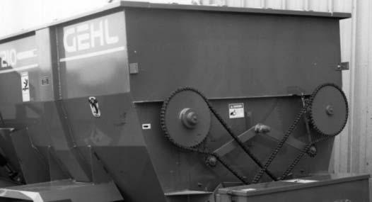
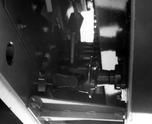
DRIVE CHAINS (Fig. 19)
Spring-loaded Idler Sprockets are provided to maintain proper operating tension at all times. Tension should be checked after every 50 hours of operation but it should remain properly adjusted throughout the life of the Chain and require NO further readjustment. Make sure that the Idler Pivots do NOT bind and are kept properly lubricated.
NOTE: If Idler fails to maintain proper tension, remove Chain Links or replace worn Chain.
LOWER AUGER POSITION (Figs. 19, 20 & 21)
Caution
BE SURE to exercise the MANDATORY SAFETY SHUTDOWN PROCEDURE (page 8), BEFORE getting into the Mixer Feeder to place the 3/8 Plain Washers under the Lower Auger Flighting.
The positions of the Lower Augers can be vertically adjusted by repositioning the Bearings in the front of the unit. In the rear of the unit, the positions of the Auger can be adjusted with the top and bottom Adjustment Nuts and Take-up Bolts on each side of the Chaincase. When properly adjusted, the Augers should be approximately 1/16” (1.6 mm) away from the Troughs, along their entire lengths.
The correct measurement of this distance can be obtained by placing 3/8 Plain Washers under the Auger Flighting in the middle and on each end of both Lower Augers and tightening the Bearings and Adjusting Nuts with the Augers resting on the 3/8 Plain Washers.
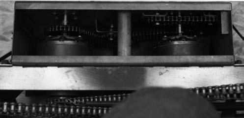
PLANETARY GEARCASE DRIVE CHAINS (Fig. 22)
The two Planetary Gearcase Drive Chains are provided with Chain Idlers for maintaining proper operating tension. Chain tension should be checked and readjusted, if necessary, after every 50 hours of operation. To readjust Chain tension, slightly loosen the appropriate Idler Sprocket Mounting bolt, so that the Idler can just be moved by tapping on the Idler Sprocket with a rubber mallet or lead hammer. Proper tension is achieved when the Chain can be deflected 1/2” (13 mm) on the strand of Chain between the Idler and Drive Sprocket. After the desired tension is adjusted, retighten the Idler mounting bolt.
Chapter 8 Lubrication Warning
NEVER attempt to lubricate the machine when any part of the unit is in motion. ALWAYS BE SURE to exercise the MANDATORY SAFETY SHUTDOWN PROCEDURE (page 8) BEFORE proceeding to lubricate this machine.
It is well to remember that a sufficient amount of oil or grease will prevent excessive part wear and early failure.
Chain Case
Maintain the proper Chain Case oil level with SAE 10W40 oil, or equivalent, at all times. All Chaincases should be maintained with an oil level at about the center of the lower Drive Shaft. The oil level can be checked or oil can be added by unlatching and opening the Chain Case Cover. The oil should be removed and new oil installed, after every 500 hours of operation, or annually. BE SURE to replace and tightly secure the Drain Plug before installing new oil.
Greasing
Wipe dirt from the Fittings before greasing to prevent any dirt from being forced into the Bearings or pivots.
Replace any missing Fittings, when noted. To minimize dirt build-up, avoid excessive greasing.
NOTE: In addition to the Fittings, inspect and repack the Trailer-Mounted unit Wheel Bearings yearly.
Oiling
Lubricate all Drive Chains every 50 hours of operation using a good grade of foaming aerosol lubricant. The recommended method is to spray the entire length of Chain on the center of the Rollers. It is better to lubricate Chains when they are warm (after use, rather than before).
In addition to the Roller Chains, apply oil or foaming aerosol lubricant to the Telescoping PTO Drive Guard.
Planetary Gearcase
The two Planetary Gearcases are filled from the factory with 80W90 oil. The oil level should be checked after every 50 hours of operation (or monthly) and maintained to a level just below the Fill Plug opening on each Gearcase.
SELF-CONTAINED HYDRAULICS RESERVOIR
NOTE: For details on the Self-contained Hydraulics system , refer to the Truck-Mounted Mixer Feeder Supplement, Form No. 907062.
Grease Fitting Locations
NOTE: For the first week of operation, lubricate all Fittings daily or after every three loads to insure proper break-in of the Drive components. Thereafter, lubricate all Fittings at the prescribed intervals of operation listed. Use a good grade of lithiumbased grease. Do NOT overlube the flanged-type Bearings.
Grease Every 10 Hours (or Daily)
1.* Telescoping PTO Drive Crosses (2 Places)
2.* CV Joint Housing (2 Places)
Grease Every 50 Hours
3.* Telescoping Drive Tube
4.** Two Piece Discharge Right & Left Conveyor Junction Pivot (2 Places)
Grease Every 100 Hours
5.* Drive Shaft Remote Center Bearing
6.* Drive Shaft Rear Bearings ( 2 Places)
7.Right Upper Auger Front Bearing
8.Right Upper Auger Rear Bearing
9.Left Upper Auger Front Bearing
10.Left Upper Auger Rear Bearing
11.Right Lower Auger Front Bearing
12.Right Planetary Input Shaft Bearing
13.Left Lower Auger Front Bearing
14.Left Planetary Input Shaft Bearing
15.** One Piece Discharge Right & Left Upper Conveyor Shaft Bearings (2 Places)
16.** One Piece Discharge Right & Left Lower Conveyor Shaft Bearings (2 Places)
17.** Two Piece Discharge Right & Left Upper Conveyor Shaft Bearings (2 Places)
18.** Two Piece Discharge Right & Left Lower Conveyor Shaft Bearings (2 Places)
19.* Drive Shaft Front Bearing
20.* Drive Shaft Remote Forward Bearing (All Models Except 7210)
* Applies only to Trailer-type units.
** Does NOT apply to Stationary units.