24 minute read
NOTES

GENERAL INFORMATION Care and Servicing
Warning
Instructions are necessary before operating or servicing the machine. Read and understand this entire manual. Follow warnings and instructions for operation and maintenance. Check for correct function after adjustments or maintenance. Failure to follow instructions can result in injury or death.
Warning
Be sure you are familiar with all safety devices and controls before operating or servicing the machine. Know how to stop before starting. This machine is designed for use only with approved accessories or referral attachments. Manitou Americas, Inc. cannot be responsible for safety if the unit is used with non-approved attachments.
Warning
Hydraulic reservoir is under pressure. Avoid contact with leaking hydraulic fluid and diesel fuel under pressure. It can penetrate the skin and eyes.
Care and servicing have a significant influence on the readiness for operation and service life of the machine. For additional service information about the engine, see the service manual provided with the machine. Use of lubricants that do not correspond to the manufacturer’s recommendations may invalidate warranty claims.
More frequent servicing, other than the recommended intervals, may be required under extreme operational conditions (extremely dusty or hot conditions).
Always dispose of waste lubrication oils and hydraulic fluids according to local regulations or take to a recycling center for proper disposal. DO NOT pour fluids onto the ground or down a drain.
DO NOT power wash the main hydraulic pumps and controls, throttle solenoids and sealed bearings. High pressure water can be forced through seals and trapped within these components, causing premature failure.
The operating pressure settings of the hydraulic system should only be adjusted by trained, qualified personnel. If malfunctions are caused by unauthorized alteration of operating pressure settings, all warranty responsibilities of the manufacturer are invalidated.
Maintenance Safety
•Never service the machine without reading the applicable instructions.
•Always lower bucket and dozer blade to the ground before performing any maintenance.
•Use correct procedures to lift and support the machine. Always lift the blade fully before installing jackstands.
•Keep engine cover and hydraulic valve cover closed except for service. Close and latch covers before operating the machine.
•Be sure to have area properly ventilated when grinding or welding parts. Wear a dust mask.
•Exhaust fumes can kill. Exhaust system must be tightly sealed. If working in an enclosed area, vent exhaust to outside when engine must be run for service.
•Never modify equipment or add unapproved attachments.
•Before checking fluid levels, stop engine and let cool, and then clean any flammable materials from the engine and engine compartment.
•Never service or adjust machine with the engine running unless the service procedure requires it.
•Avoid contact with leaking hydraulic fluid and diesel fuel under pressure, which can penetrate the skin and eyes. NEVER use your hands to search for hydraulic fluid leaks; use a piece of paper or cardboard. Escaping fluid under pressure can be invisible and can penetrate skin and cause serious injury. If any fluid is injected into your skin, get immediate medical attention. Injected fluid MUST be surgically removed or gangrene may result.
•Never fill fuel tank with engine running, while smoking or when near open flame.
•Wipe up fuel spills immediately.
•Keep body, jewelry and clothing away from moving parts, electrical contacts, hot parts and exhaust.
•Wear eye protection when servicing the machine.
•Lead-acid batteries produce flammable and explosive gas. Keep arcs, sparks, flames and lighted tobacco away from batteries.
•Batteries contain acid, which burns eyes and skin on contact. Wear protective clothing. If acid contacts body, flush well with water. For eye contact, flush well with water and get immediate medical attention.
Maintenance Label Symbols
Symbol Assembly Explanation
GeneralVisual check
GeneralLubrication instructions
Fuel systemDrain condensation water
Fuel systemReplace the fuel filter; clean the fuel pre-filter
RadiatorCheck the coolant level
RadiatorChange coolant
EngineCheck valve clearance; adjust if necessary
EngineCheck engine oil level
EngineChange engine oil
EngineReplace oil filter
EngineCheck V-belt tension
Travel driveChange final drive oil
Travel driveCheck final drive oil level
UndercarriageCheck track tension
Hydraulic systemCheck hydraulic oil level
Hydraulic systemChange hydraulic oil
Hydraulic systemReplace hydraulic oil filter; replace hydraulic reservoir breather filter
Radiator finsClean radiator fins
Heating, air conditioning Replace the cab air filter
Maintenance Schedule
The following service schedule is a recommended. Maintenance work must be done at regular intervals. Failure to perform scheduled maintenance work will result in excessive wear and early machine failures. The following service schedule is a recommended.
a.After emptying the tank, water must be removed and air must be purged from the fuel system before use. See “Fuel Shut-off Valve and Water Separator” on page4-13 and “Purging Air from the Fuel System” on page4-13.
Check,Clean&Inspect(Cont.)
Fluid and Filter Changes
a.Change after first 50 hrs; every 500 hrs thereafter.
b.Dusty work environment, high temperature, high rate of hammer use, and similar intensive use conditions.
c.Change after first 50 hrs; every 500 hrs thereafter.
d.Change after first 50 hrs; every 1000 hrs thereafter.
Cab Air Conditioning
Figure 4-1 Lubrication Points

Recommended Lubricants
Engine Oil
Important
Be sure to read the engine manual supplied with this machine for detailed engine specifications.
See “Fluid Capacities/Lubricants” on page1-4 for engine oil specifications.
Hydraulic Oil
See “Fluid Capacities/Lubricants” on page1-4 for hydraulic oil specifications.
Swing Ring
Lubricate with a heavy-duty lithium complex grease with 3% molybdenum disulfide, such as Chevron RPM Heavy Duty Grease No. 2, Mobilgrease Moly 52 or BP Energrease Moly EP2.
Final Drive Unit
An EP grade gear oil that conforms to API GL5, such as Chevron Delo Gear 80W-90 or BP Transgear 80W90 is required.
Swing Gear Unit
An EP grade gear oil that conforms to API GL5, such as Chevron Delo Gear 80W-90 or BP Transgear 80W90 is required.
Lubrication Points
See Figure 4-1.
Grease all lubrications points using a heavy-duty lithium complex grease with 3% molybdenum disulfide, such as Chevron RPM Heavy Duty Grease No. 2, Mobilgrease Moly 52 or BP Energrease Moly EP2.
Ranges of Applications
From –13° F to +104° F (-25° C to + 40° C) outside temperature.
Engine
Important
Be sure to read the service manual supplied
Checking Engine Oil Level
Important
See “Fluid Capacities/Lubricants” on page1-4 for engine oil grade. To prevent damage to the engine, only use the engine oils specified, or oils of equivalent quality and grade could occur.
To check the engine oil, the machine must be on a level surface with the engine turned off. Check the oil level before starting the engine or at least five minutes after shutting off the engine.
1.Open the engine cover.
2.Check the engine oil level using the dipstick (1) located at front of the engine. See Figure 4-2.

3.Add oil if required through the oil filler neck (3). See Figure 4-2.
4.Drain excess oil if required. See “Changing Engine Oil and Filter” on page4-10.
Figure 4-2 Oil Dipstick and Filter Locations
Note: The marks on the dipstick indicate the minimum and maximum oil levels.
Changing Engine Oil and Filter
1.Perform the “Mandatory Safety Shutdown Procedure” on page2-2, but do not allow the engine to fully cool; warm oil will drain more completely..
Important
The machine must be postioned on a level surface for the oil to drain completely.
2.Open the engine cover.
3.Position waste oil collection container under engine oil pan.
4.Remove the drain plug from the oil pan and allow oil to drain into waste oil collection container.
Important
Dispose of waste engine oil according to environmental laws or take to a recycling center for proper disposal. DO NOT pour waste engine oil onto the ground or down a drain.
5.Remove the oil filter (2, Figure 4-2), using a filter wrench as necessary.
6.Clean the filter housing surface. Put a film of clean oil on the filter gasket. Install the new filter and tighten 1/2 rotation past where the filter contacts the filter mounting surface.
7.Reinstall the drain plug.
8.Clean the area around the oil filler cap.
9.Remove the oil fill cap from the engine. Pour in new oil. Crankcase capacity is 8.2 qts. (7.8 L). Do NOT fill crankcase above the MAX mark on the dipstick.
10.Reinstall oil filler cap.
11.Start the engine and let it run for several minutes. Watch the engine oil light on the control panel. The light should turn off after several seconds. If it does not, shut off engine and determine cause.
12.Stop the engine and check for leaks at the oil filter and oil drain plug.
13.Check the oil level again and add oil if necessary.
Air Cleaner Service
1.Perform the “Mandatory Safety Shutdown Procedure” on page2-2,
2.The air cleaner is located under the engine cover. Press the engine cover release button and raise the engine cover.
3.Release the bow clips (1) to remove the air cleaner cover and gasket (2). See Figure 4-3.
4.Carefully remove outer air cleaner element (3). See Figure 4-3. Carefully remove inner air cleaner element (3). Clean the inside of the air cleaner housing components with a lint-free cloth. Clean all contamination (dust) from inside the upper and lower air cleaner housing and cover with a clean, lint-free cloth.

5.Replace both the inner and outer air cleaner elements when the indicator light comes on or according to the maintenance schedule.
6.Reinstall air cleaner elements (3, 4), gasket and air cleaner cover (2). Fasten bow clips (1).
7.Close and secure engine cover.
Important
Do not knock the element against a solid object to remove dust. The element may become distorted and damaged.
Important
Do not operate engine without the air cleaner components installed or damage to the engine could occur.
Fuel System
Filling the Fuel Tank
Warning
Stop the engine and allow it to cool before filling the fuel tank. NO SMOKING! Failure to obey warnings can cause an explosion or fire.
The fuel level in the tank is indicated by the fuel gauge (1) on the console. See Figure 4-4.
To fill the tank, remove the fuel filler cap (2) located on the left rear of the unit behind the cab by rotating the lock cover (3) and inserting the ignition key into the lock and unlocking the cap. See Figure 4-4. Fill using clean diesel fuel with a cetane rating over 45. Re-install fuel cap.

Fuel Filter
Important
Unless draining fuel tank for servicing, never operate the machine until the fuel tank is completely empty. The fuel system has to be bled of air whenever the fuel tank is run empty. Always fill the fuel tank after use.
Important
When using the machine in cold weather, it is important to use the proper fuel blend to prevent fuel “gelling”. See the engine operator’s manual for fuel blend information related to temperature. Fuel gelling can permanently clog the fuel filter and water separator elements, requiring replacement.
Warning
Always clean up spilled fuel and oil. Keep heat, flames, sparks and lighted tobacco away from fuel and oil. Failure to use care around combustibles can cause explosion or fire, which can result in injury or death.
Danger
When handling fuel, there is a high risk of fire. Never work on the fuel system around open flames or sparks. DO NOT smoke when working on the fuel system or refueling. Before refueling, turn off the engine and remove the ignition key. Do not refuel in closed rooms. Wipe up fuel spills immediately. Keep the machine clean to reduce the risk of fire.
Warning
Use care to catch any spilled fuel when servicing the fuel filter. Spilled fuel can cause a fire.
The fuel filter is located behind and below the engine cover.
1.Perform the “Mandatory Safety Shutdown Procedure” on page2-2,
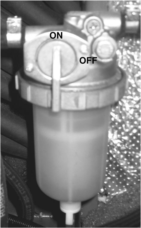
2.Shut off fuel using the shut-off valve (2, Figure 45) on the water separator.

3.Clean dirt from the housing and unscrew the fuel filter element (1, Figure 4-6).
4.Remove and discard old filter element properly.
5.Clean around the filter housing.
6.Coat the seal on the new fuel filter with clean engine oil.
7.Install the new fuel filter and tighten 1/2 rotation past where the filter contacts the filter mounting surface.
8.Twist the fuel shut-off valve (2, Figure 4-5) on the water separator counter-clockwise to the “ON” position.
The fuel system must be purged of air after changing the fuel filter, or if the fuel tank has been run dry. See “Purging Air from the Fuel System” on page4-13.
Fuel Shut-off Valve and Water Separator
If water is seen in the plastic water separator bowl or the indicator ring rises to position (3), the water will need to be drained. See Figure 4-7.
Note: The water separator is located behind the engine underneath the engine cover.
1.Twist the fuel shut-off valve lever (2, Figure 4-7) on the water separator clockwise to the “OFF” position.
Purging Air from the Fuel System
Warning
DO NOT air bleed a hot engine. Spilled fuel can cause a fire.
Starting from the fuel tank, the fuel system runs through the water separator, fuel filter, fuel injection pump and high pressure piping to the fuel injection nozzles. If the fuel tank is run dry, or if the fuel filter, water separator or fuel lines are replaced, trapped air must be removed, or bled, from the fuel system. Bleed air from the fuel system according to the following steps:

1.Fill the fuel tank.
2.Make sure that the valve on the water separator (2, Figure 4-7) is in the “open” (ON) position.
3.Turn the ignition key to the “I” (ON) position.
4.Wait about five minutes while the fuel system automatically bleeds itself.
5.Start the engine.
If the engine runs smoothly and then stops, or if it does not run smoothly, switch off the engine and bleed the system again as described in this procedure. If the engine still does not run smoothly, contact your dealer.
2.Unscrew plug (4) and collect the water that drains out of the water separator. Allow water to drain until the indicator ring returns to the bottom of the water separator.
3.Tighten plug (4) and discard fuel/water according to local regulations. DO NOT pour fluids onto the ground or down a drain.
4.Twist the fuel shut-off valve (2) on the water separator to the (ON) position.
Cooling System
Checking Coolant Level
Note: Engine must be cold.
1.Perform the “Mandatory Safety Shutdown Procedure” on page2-2,
2.Open the engine cover.
3.Check the coolant level in the expansion reservoir. See Figure 4-8 for the 503Z, or Figure 4-9 for the 603.

4.If low, (2), Figure 4-8 for the 503Z, or Figure 4-9 for the 603, remove cap and overflow tube.

5.Fill reservoir to FULL line (1). Refer to “Fluid Capacities/Lubricants” on page1-4 for the correct coolant type and to “Coolant Compound Table” on page1-8 for the correct coolant mixture. Replace the reservoir cap.

Electrical System
Warning
Inspect and check the machine’s electrical equipment at regular intervals. Defects, such as loose connections or scorched cables much be repaired before using the machine. Work on the machine’s electrical system must be done only by a trained technician.
Fuses
The fuse panel is located on the right consoles. See (1) Figure 4-10.
To replace a fuse, remove the panel cover and pull the old fuse from the socket. Install a new fuse of the same rating and re-install the fuse panel cover.
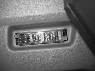
Important
Blown fuses indicate electrical system malfunctions. Determine what caused the fuse to blow and repair the problem before replacing the fuse.
Refer to page 1-6 for fuse identification.
SerialNumbers AJ02993andup
Locatedoninsideof rightcab/canopy interiortrim
SerialNumbersto AH02282
Locatedontopofright insidecab/canopy interiortrim.
Warning
Before servicing the battery or electrical system, disconnect battery from the electrical system by turning the battery disconnect switch to the “OFF” position.
Explosive gas is produced while a battery is in use or being charged. Keep flames or sparks away from the battery area. ALWAYS charge the battery in a wellventilated area. Do not jump-start a frozen battery, or it may explode. A discharged battery can freeze at 14°F (10°C).
To prevent short circuits keep metal parts on your clothing and metal watchbands away from the positive (+) terminal of the battery.
Warning
Never lay a metal object on top of a battery, because a short circuit can result. Battery acid is harmful to skin and fabrics. If acid spills, follow these first-aid tips:
Immediately remove any clothing on which acid spill.
•If acid contacts skin, rinse the affected area with running water for 10 to 15 minutes.
•If acid contacts eyes, flood eyes with running water for 10 to 15 minutes. See a doctor at once. Never use any medication or eye drops unless prescribed by the doctor.
•To neutralize acid spilled on the floor, use one of the following mixtures:
•0.5 kg (1 lbs.) of baking soda in 4 L (4 qts.) of water.
•0.5 L (0.5 qts.) of household ammonia in 4 L (4 qts.) of water.
Battery In case of acid contact, wash immediately with water for several minutes. In case of eye contact, get medical attention immediately.
Model 503Z – serial numbers AH02282 and before: the battery (1, Figure 4-11) is located under the engine cover in front of the oil cooler.
Model 503Z excavators – serial number AJ02993 and up and Model 603 – all serial numbers: the battery (2, Figure 4-11) is located under the cab near the rear of the undercarriage.
Battery cables must be clean and tight. Remove any acid or corrosion from the battery and cables using a sodium bicarbonate and water solution. Cover the battery terminals and cable ends with battery-saver grease. Note: The battery is maintenance-free and requires no other service.
Using a Booster Battery (Jump-Starting)
Use care when jump-starting the machine. The booster battery must be 12-volt.
Warning
•Keep arcs, sparks, flames and lighted tobacco away from batteries. When jump-starting from a booster battery, make final connection (negative) at engine frame away from the battery. A discharged battery can create flammable gases. Sparks or open flames can cause this gas, and the battery, to explode.
•DO NOT jump-start or charge a frozen battery. Warm battery to 60°F (16°C) before connecting to a charger. Unplug charger before connecting or disconnecting cables to battery.
Important
When jump-starting from another machine, be sure the second machine is not running while using the unstarted machine’s glow plugs. High voltage spikes from a running machine can burn out the glow plugs.
Important
Damage to the electrical system can occur if:
•the engine is operated with the battery cables disconnected,
•the battery cables are connected when using a fast charger or when welding on the machine (When welding on the machine, remove both cables from the battery and ground the welder to the machine frame near the repair area), or
•battery booster cables are connected incorrectly.
503Z (Serial Numbers up to AH02282) Jump-Start Procedure:
1.Turn ignition key to the “OFF” position.
2.Open the engine cover.
3.Connect one end of the cable to the positive (+) terminal on the booster battery. Connect the other end of the same cable to the positive (+) terminal on the battery of the machine to be started.
4.Connect one end of the second cable to the negative (-) terminal on the booster battery. Connect the other end of the same cable to the frame of the machine to be started.
5.Start the engine. After the engine is running, remove the cable connected to the frame first. Disconnect the other cable from the machine battery positive (+) terminal.


6.Close the engine cover.
503Z (Serial Numbers AH00579 and up) and 603 (All Serial Numbers) Jump Start Procedure:
1.Ensure the battery disconnection switch is turned to the “ON” position.
2.Turn ignition key to the “OFF” position.
3.Open the engine cover.
4.Slide the boot (7, Figure 4-12) down cable (6) to expose terminal (3) on the battery disconnect switch.
Note: Cable (6), connected to terminal (3) on the battery disconnect switch, is also connected to the positive (+) terminal on the starter.
5.Connect one end of the cable to the positive (+) terminal on the booster battery. Connect the other end of the same cable to terminal (3) on the battery disconnect switch.
Warning
Stay away from moving components when the engine is running. Use extreme caution when removing jumper cables and when replacing boot (7, Figure 4-12) over terminal (3) on the battery disconnect switch. Severe injury can result.
8.Staying clear of moving components, carefully replace boot (7, Figure 4-12) back over terminal (3) on the battery disconnect switch.
9.Close the engine cover.
Hydraulic System
Warning
6.Connect one end of the second cable to the negative (-) terminal on the booster battery. Connect the other end of the same cable to the frame of the machine to be started.
7.Start the engine. After the engine is running, remove the cable connected to the frame first. Disconnect the other cable from the terminal (3) on the battery disconnect switch. See Figure 4-11.
Important
DO NOT allow the cable ends to touch when removing them from the batteries. Arcs and direct short circuits can cause severe damage to the electrical system of the running machine.
Hydraulic reservoir is under pressure. Never use your hands to search for hydraulic fluid leaks; use a piece of paper or cardboard to find leaks. Escaping fluid under pressure can be invisible and can penetrate the skin, causing serious injury. If any fluid is injected into your skin, get immediate medical attention Injected fluid MUST be surgically removed or gangrene may result.
Checking Hydraulic Oil Level
1.Run the machine until the hydraulic system has reached operating temperature. Position the machine on a level surface.
2.Fully extend the bucket and boom, retract arm and position as shown in Figure 4-13.
3.Lower the bucket and dozer blade to the ground. Engage the parking brake.
4.Shut off the engine. Remove the ignition key and take it with you. Lock-out the controls by raising left control console.

5.Open the engine cover. Check the hydraulic oil level indicator tube (1, Figure 4-16) in the back corner of the engine compartment. Oil level should be visible in the sight gauge (2).
6. If the hydraulic oil level is low: a.Remove the three screws with lockwashers securing the fuel tank/hydraulic reservoir cover. Remove the tank/hydraulic reservoir cover. Place the cover away from the work area to protect it from damage. b.Assemble the tools included in the tool kit as shown in Figure 4-15. The short hex shaft tool (6) is designed to fit the hydraulic oil reservoir filler cap. c.Using the assembled tools, slowly open the hydraulic oil filler cap (4, Figure 4-16) to allow pressure to escape from the hydraulic system.


Warning
The hydraulic reservoir is under pressure. Removing the cap to quickly can cause hot oil to be ejected from the hydraulic oil fillter opening. Carefully loosen the oil filler cap slowly to relieve pressure.
d.Remove the oil filler cap (4).
e.With the filter insert (5) in place, add hydraulic oil until oil level is between the marks on sight gauge (2).
f.Re-install hydraulic oil filter insert and filler cap and tighten securely.
g.Replace the fuel tank/hydraulic reservoir cover and secure it with the three screws with lockwashers removed earlier.
h.Close the engine cover.
i.Start the engine and let it idle for a few minutes.
j.Check hydraulic functions. Repeat this procedure to recheck the hydraulic oil level.
Changing Hydraulic Oil
1.Position the machine on a level surface.
2.Fully extend the bucket and boom, and retract arm as shown in Figure 4-13. Lower bucket and dozer blade to the ground. Turn off the machine.
3.Perform steps 6, a through c in “Checking Hydraulic Oil Level” on page4-17
4.Remove filter insert (5, Figure 4-16).
5.Open the reservoir drain plug and drain oil into a suitable container. Re-install drain plug and tighten securely.
Important
Note: The hydraulic oil level varies according to machine operating temperature. When the machine is cold before starting, the level should be near the LOW mark; when at normal operating temperature, the level should be near the FULL mark.
Warning
Do not overfill the hydraulic reservoir. Damage to the system, high-pressure leaks and injury can result.

Always dispose of hydraulic fluids according to local regulations or take to a recycling center for proper disposal. DO NOT
6.Reinstall filter insert (5).
7.Fill reservoir with hydraulic oil until oil level is between marks on sight gauge.
8.Replace the fuel tank/hydraulic reservoir cover and secure with the three screws with lockwashers removed earlier.
9.Close the engine cover.
10.Start the engine and let it idle for a few minutes. Cycle all front attachment hydraulic functions and recheck hydraulic oil level.
Hydraulic Cooling System
The hydraulic system uses a hydraulic cooler to keep the hydraulic fluid at the proper temperature. The cooler is located inside the engine compartment near the engine radiator. Inspect the cooler for leaks or damage.
Pilot Valve
Important
Hydraulic oil contamination can damage pilot valve control spools. Check the pilot control valve filter/restrictor every 1000 hours and clean if necessary. Replace the filter/restrictor if it is damaged in any way.

Checking Pilot Control Valve Filter:
1.Position the machine on a level surface.
2.Fully extend the bucket and boom, retract the arm and position as shown in Figure 4-13.
3.Lower the bucket and dozer blade to the ground. Move the joysticks in all directions to verify the hydraulic system is de-pressurized.
4.Shut off the engine. Remove the ignition key and take it with you. Lock-out the controls by raising left control console.
5.To relieve pressure, slowly open the hydraulic oil filler cap (4). Re-tighten the filler cap after relieving pressure.
6.Tilt the cab/canopy according to “Tilting the Cab or Canopy” on page3-15.
7.Disconnect hose (A, Figure 4-17) connected to the pilot control filter/restrictor fitting (B) on the side of a joystick control valve.
Important
Hydraulic oil will leak during this procedure. Place absorbent material under valve to catch leaking oil. Always dispose of hydraulic fluids according to environmental laws or take to a recycling center for proper disposal.
8.Disconnect the pilot control filter/restrictor fitting (B) from the valve.
9.Check the filter/restrictor fitting filter screen (C) for contamination/dirt and clean if necessary. Replace the filter/restrictor if it is damaged.
10.Replace filter/restrictor fitting (B) back into the valve, and reconnect hose to the filter/restrictor (C). Tighten securely.
11.Repeat steps 7-10 for the other joystick control valve.
12.Tilt the cab/canopy down according to “Tilting the Cab or Canopy” on page3-15.
Warning
•Hydraulic hoses and connections must be inspected by a trained technician before the first use of the machine, and at least annually thereafter, for leaks and/or damage.
•Leakages and damaged pressure lines must be immediately repaired or replaced by an authorized service center.
•Never use your hands to check for suspected hydraulic leaks. Always use a piece of wood or cardboard.
•Leaks from hydraulic hoses or pressurized components can be difficult to see, but pressurized oil can have enough force to pierce the skin and cause serious injury.
•Obtain immediate medical attention if pressurized oil pierces the skin. Failure to obtain prompt medical assistance could result in gangrene or other serious damage to tissue.
•Always relieve hydraulic system pressure before performing any maintenance on the machine. Do not tighten leaking connections when the hydraulic system is under pressure.
•Never weld or solder damaged or leaking pressure lines and/or screw connections. Always replace damaged hydraulic components.
•Hydraulic hoses must be replaced every six years from the date of manufacture, even if they do not appear damaged. The date of manufacture (month or quarter and year) is indicated on hydraulic hoses. See Figure 4-18.

Checking and Adjusting V-Belt Tension
1.Position the machine on a level surface.
2.Lower the bucket and dozer blade to the ground. Move the joysticks in all directions to verify the hydraulic system is de-pressurized.
3.Shut off the engine. Remove the ignition key and take it with you. Lock-out the controls by raising left control console.
4.Wait for the engine to cool and open the engine cover and carefully inspect the V-belt (1) for damage. If the V-belt (1) is damaged, have it replaced by your dealer.
5.Press on the center of a span on the V-belt to check deflection. The belt deflection should be no more than 5/16” (8 mm). See Figure 4-19.
6.If deflection is more than 5/16” (8 mm): a.Loosen adjustment bolt (2) and rotate the alternator (3) in the direction of the arrow until reaching the correct V-belt tension. b.Tighten adjustment bolt (2) and re-check Vbelt tension. Close the engine cover when finished.


Checking and Adjusting Air Conditioning V-Belt Tension
1.Position the machine on a level surface.
2.Lower the bucket and dozer blade to the ground. Move the joysticks in all directions to verify the hydraulic system is de-pressurized.
3.Shut off the engine. Remove the ignition key and take it with you. Lock-out the controls by raising left control console.
4.Wait for the engine to cool and open the engine cover and carefully inspect the V-belt (1) for damage. If the V-belt (1) is damaged, have it replaced by your dealer.
5.Press on the center of a span on the air conditioning V-belt to check deflection. The belt deflection should be no more than 11/32” (9 mm). See Figure 4-20.
6.If deflection is more than 11/32” (9 mm): a.Loosen jam nut (2) and rotate the adjustment nut (3) until reaching the correct V-belt tension. b.Tighten jam nut (2) and re-check V-belt tension. Close the engine cover when finished.
Track System
Track Cleaning
If dirt or mud builds up in the track frame, raise the track frame using the boom and dipper arm and then rotate the elevated track to clean it. Be sure that the build-up has been cleared from the track. Repeat for the other track. See Figure 4-21.
Figure 4-21 Track Cleaning
Note: When using the boom and dipper arm to lift any portion of the machine, roll the bucket until the round base is against the ground. The angle of the arm to the boom should be at 90º. See Figure 4-21.
Changing Final Drive Oil
1.Position the machine on a level surface with final drive plugs positioned as shown in “Drain Position,” Figure 4-22. Turn off the engine.
2.Open both plugs and drain oil into a suitable container. Re-install plugs.
Important
Always dispose of oil according to local regulations or take to a recycling center for proper disposal. DO NOT pour fluids onto the ground or down a drain.
3.Start the engine and move the machine slightly until plugs are positioned as shown in “Fill Position,” Figure 4-22.

4.Shut off the engine. Remove the ignition key and take it with you. Lock-out the controls by raising left control console.
5.Remove both screw plugs. Pour fresh oil (Chevron Delo Gear 80W-90 or BP Transgear 80W-90) into the top hole until oil starts to run out of the bottom hole.
6.Re-install both plugs securely.
Checking and Adjusting Track Tension
1.Position the machine on a level surface. On machines equipped with rubber tracks, position the excavator so the tracks are positioned with mark (1, Figure 4-23) on the top span of the track in between drive pinion (2) and track tension roller (3).

2.Use the bucket and dozer blade to lift the unit up until tracks are just clear of the ground as shown in Figure 4-24.
3.Shut off the engine. Remove the ignition key and take it with you. Lock-out the controls by raising left control console.
4.Measure the clearance at the raised track roller from the drive gear. Deflection should be between 3/4”-1” (20-25 mm).
5.Using a grease gun, pump grease into the fitting until the track is properly tensioned (Figure 4-24).
Note: A grease gun is supplied with machine tool kit.
Important
Do not over-tension the track. If track is too tight, loosen the grease fitting to relieve pressure.

Warning
Do not loosen grease fitting more than two turns, or grease fitting could be ejected under pressure and cause injury. Keep your face and body away from the fitting when loosening.
6.Start the engine. Lower the unit to the ground.
7.Repeat this procedure for the other track.
Windshield Washer Fluid
1.Shut off the engine. Remove the ignition key and take it with you. Lock-out the controls by raising left control console.
2. Open the engine cover.
3.Locate the windshield washer reservoir (Figure 425), above the radiator.
4.Open the windshield washer reservoir cover (1, Figure 4-25) and fill the tank with windshield washer fluid.
5.Close the windshield washer tank cover securely.
6.Close and latch the engine cover.
LONG-TERM STORAGE
If storing the machine for a long period (longer than two months), perform the procedures in this section.
Before Storage
1.Wash the entire machine.
2.Lubricate all grease zerks. See “Lubrication Points” on page4-9.
3.Change the engine oil and filter according to “Changing Engine Oil and Filter” on page4-10.
4.Add a fuel stabilizer to the fuel system according to the fuel supplier’s recommendations.
5.Remove and fully charge the battery. Store the battery in a cool, dry location.

6.If the machine will not be operated for a month or longer, apply grease to all exposed hydraulic cylinder rod areas or retract all cylinders so rod exposure is minimized. Apply grease to any remaining rod areas.
7.If the ambient temperature (at any time during the storage period) is expected to drop below freezing, make sure the engine coolant is either completely drained from the radiator and engine block or that the amount of anti-freeze in it is adequate to keep the coolant from freezing. Refer to the engine manual for anti-freeze recommendations and quantities.
8.Protect against extreme weather conditions such as moisture, sunlight and temperature.
During Storage
About once each month, connect the battery and check all fluid levels to make sure they are at the proper level before starting the engine.
Start the engine and allow it to run until it warms up and then move the machine a short distance to help relubricate the internal parts. Run the engine until the battery has a chance to recharge and then shut it off.
Important
If it is desired to operate the hydraulic cylinders at this time, BE SURE to wipe the protective grease (and any adhering dirt) from the cylinder rods prior to starting the engine. After operating, BE SURE to recoat the cylinder rods with grease if the machine is to be returned to storage.
After Storage
After removing the machine from storage and before operating it, perform the following:
1.Replace and re-connect the battery.
2.Wipe off grease (and any adhering dirt) from cylinder rods.
3.Check V-belt tension.
4.Check all fluid levels and top-off as necessary.
5.Start the engine. Observe all indicators. If all indicators are functioning properly and reading normally, move the machine outside.
6.When outside, park the machine and let the engine idle for at least five minutes.
7.Shut off the engine and walk around machine. Make a visual inspection looking for evidence of leaks.Review and re-familiarize yourself with all safety precautions starting on page 2-1.
8.Follow the starting and warm-up procedures according to starting on page 3-28.