7 minute read
CHAPTER 3 – OPERATION

OPERATING CONTROLS Machine Orientation
Warning
•Read and understand this entire manual. Follow warnings and instructions for operation and maintenance. Failure to follow instructions can result in injury or death.
•Read and understand all safety decals before operating the machine. DO NOT operate the machine unless all factoryinstalled guards and shields are in place.
•Be sure you are familiar with all safety devices and controls before operating the machine.
•Know how to stop the machine before starting.
•Use only with GEHL Company approved accessories or referral attachments. GEHL Company cannot be responsible for safety if the unit is used with nonapproved attachments.
•Check for correct function after adjustments or maintenance.
Guards and Shields
Whenever possible, guards and shields are used to protect potentially hazardous areas on the machine. In many places, decals are also provided to warn of potential hazards or to display special operating procedures. See Chapter 2 – Safety.
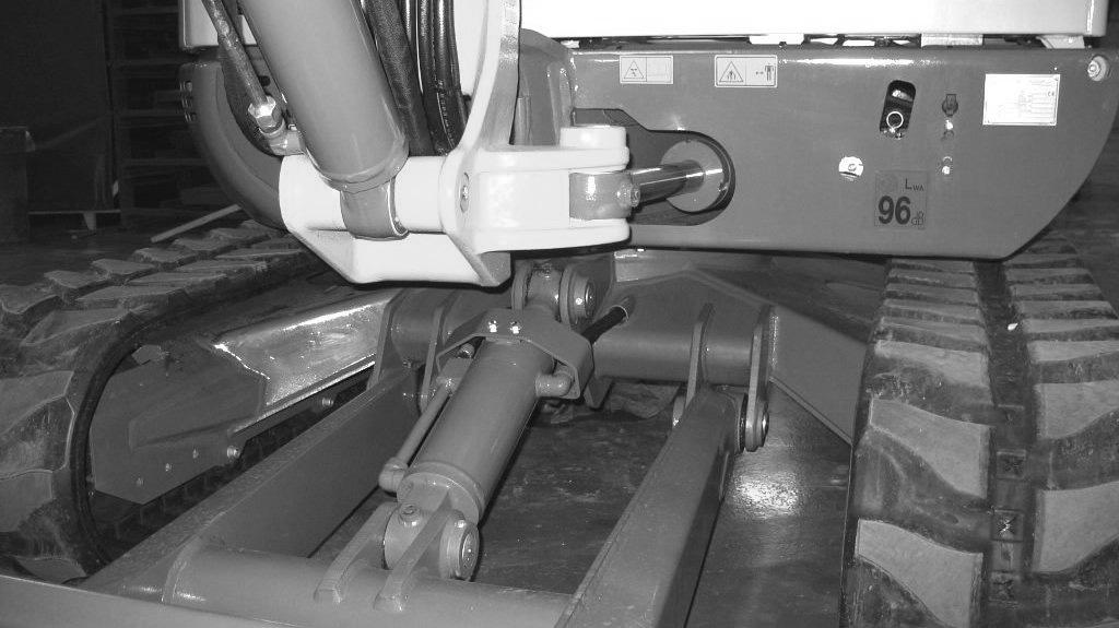
The left operator’s console should be raised to enter and exit the cab. In the raised position, the console locks out all hydraulic functions of the machine. See Figure 3-1.
Pos. Description
30 Hydraulic oil filter indicator (red) – Hydraulic oil filter indicator light comes on when hydraulic oil filter is too restricted.
31 Air filter indicator (red) – Air filter indicator light comes on when air filter is too dirty.
32 Battery charge fault indicator (red) – Battery charge indicator light comes on when the ignition is turned on and goes off when the engine starts. If the indicator light comes on while the engine is running, the battery is not charging, indicating a faulty charging circuit in the alternator or problems with the V-belt. NOTE: a faulty V-belt affects cooling pump operation, which can lead to overheating and more serious engine problems. Shut off the engine IMMEDIATELY and determine the cause if this indicator comes on when the engine is running.
33 Engine oil pressure indicator (red) – Engine oil pressure light comes on when the ignition is turned on, and goes out when the engine starts. During normal operation, this indicator should remain off. The indicator will light if the engine oil pressure drops too low. If this occurs, shut the engine off IMMEDIATELY and determine the cause of the pressure drop.
34 Coolant temperature indicator (red) – Coolant temperature indicator light comes on when coolant temperature is too high.
35 Glow plug indicator (yellow) – Glow plug indicator light comes on when the ignition key is in the glow plug activation position. Indicator will go out when the glow plugs have heated sufficiently to start the engine.
36 Hourmeter – Indicates the total operating hours of the machine. Use the hourmeter to track maintenance in the maintenance log.
37 Fuel level gauge – The fuel level gauge shows the amount of fuel in the tank.
38 Indicator light – Not assigned.
39 Hydraulic oil temperature indicator light – Hydraulic oil temperature indicator light comes on when hydraulic oil is too hot.
40 Coolant temperature gauge – Displays coolant temperature.
41 High-speed switch (transport speed) – Pressing the switch will enable high travel speed.
42 Windshield wiper switch (cab models only) – Pressing the two-position switch to the first position turns on the windshield wiper. Pressing and holding the switch in the second position activates the washer fluid pump.
43 Work light switch – Press switch to the ON position to turn on the boom work light.
44 Roof lights (option) – Press switch to the ON position to turn on the roof light lights.
45 Rotating beacon (option) – Press switch to the ON position to turn on the rotating beacon.
46 Ventilation fan (two-speed) – Press the two-position switch to turn on the ventilation fan. Pressing switch to the first position is the low fan speed position, and the second position is the high fan speed position. If the Summer/Winter operation valve is OPEN (HEATING position), this switch will function as the cab heater ON/OFF switch. The Summer/Winter operation valve is located under the hood on top of the engine behind the radiator.
47 Air conditioning (option) – Press the switch to turn on the air conditioning. 48 Proportional control status indicator (option) – One flash indicates precision mode; two flashes indicate power mode.
49 Not assigned
50 High-speed indicator (option) – Indicates high-speed is enabled.
51 Engine error indicator – Indicates a “check engine” condition. See page 5-6.
52 Auto-idle switch (option) – Enables optional auto-idle feature. See page 3-19.
Pos. Description
30 Hydraulic oil filter indicator (red) – Hydraulic oil filter indicator light comes on when hydraulic oil filter is too restricted.
31 Air filter indicator (red) – Air filter indicator light comes on when air filter is too dirty.
32 Battery charge fault indicator (red) – Battery charge indicator light comes on when the ignition is turned on and goes off when the engine starts. If the indicator light comes on while the engine is running, the battery is not charging, indicating a faulty charging circuit in the alternator or problems with the V-belt. NOTE: a faulty V-belt affects cooling pump operation, which can lead to overheating and more serious engine problems. Shut off the engine IMMEDIATELY and determine the cause if this indicator comes on when the engine is running.
33 Engine oil pressure indicator (red) – Engine oil pressure light comes on when the ignition is turned on, and goes out when the engine starts. During normal operation, this indicator should remain off. The indicator will light if the engine oil pressure drops too low. If this occurs, shut the engine off IMMEDIATELY and determine the cause of the pressure drop.
34 Coolant temperature indicator (red) – Coolant temperature indicator light comes on when coolant temperature is too high.
35 Glow plug indicator (yellow) – Glow plug indicator light comes on when the ignition key is in the glow plug activation position. Indicator will go out when the glow plugs have heated sufficiently to start the engine.
36 Hourmeter – Indicates the total operating hours of the machine. Use the hourmeter to track maintenance in the maintenance log.
37 Fuel level gauge – The fuel level gauge shows the amount of fuel in the tank.
38 Indicator light – Not assigned.
39 Hydraulic oil temperature indicator light – Hydraulic oil temperature indicator light comes on when hydraulic oil is too hot.
40 Coolant temperature gauge – Displays coolant temperature.
41 High-speed switch (transport speed) – Pressing the switch will enable high travel speed.
42 Windshield wiper switch (cab models only) – Pressing the two-position switch to the first position turns on the windshield wiper. Pressing and holding the switch in the second position activates the washer fluid pump.
43 Work light switch – Press switch to the ON position to turn on the boom work light.
44 Roof lights (option) – Press switch to the ON position to turn on the roof light lights.
45 Rotating beacon (option) – Press switch to the ON position to turn on the rotating beacon.
46 Ventilation fan (two-speed) – Press the two-position switch to turn on the ventilation fan. Pressing switch to the first position is the low fan speed position, and the second position is the high fan speed position. If the Summer/Winter operation valve is OPEN (HEATING position), this switch will function as the cab heater ON/OFF switch. The Summer/Winter operation valve is located under the hood on top of the engine behind the radiator.
47 Air conditioning (option) – Press the switch to turn on the air conditioning.
48 Proportional control status indicator (option) – One flash indicates precision mode; two flashes indicate power mode.
49 Not assigned
50 High-speed indicator (option) – Indicates high-speed is enabled.
51 Engine error indicator – Indicates a “check engine” condition. See page 5-6.
52 Auto-idle switch (option) – Enables optional auto-idle feature. See page 3-19.
Excavator Components
1.Fuel water separator
2.Battery disconnect switch (All Model 603; Model 503Z - serial numbers AH00579 and up)
3.Air cleaner
4.Fuel filter
5.Engine oil filter
6.Engine oil dipstick
7.Engine oil fill
8.Heater on/off valve (cab only serial numbers AD04650 and before)
9.Locking fuel filler cap
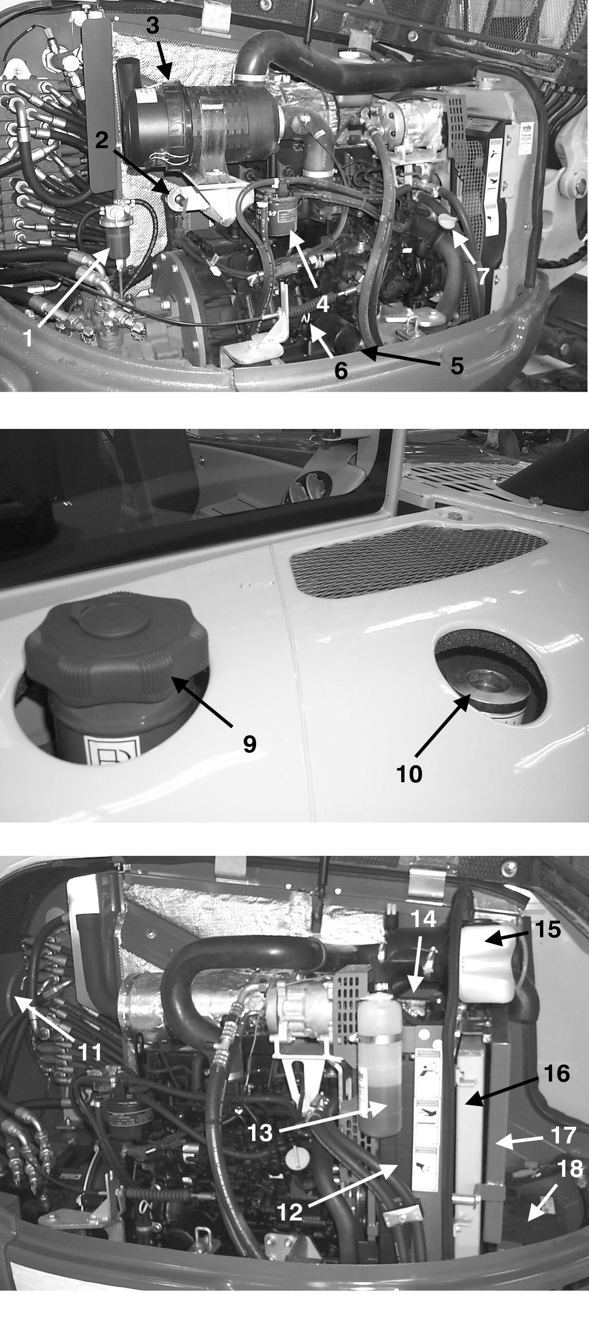
10.Hydraulic fluid filler cap
11.Hydraulic fluid level sight gauge
12.Radiator
13.Radiator overflow reservoir
14.Radiator cap
15.Windshield washer reservoir (cab only)
16.Hydraulic oil cooler
17.Air conditioning condenser (option, cab only)
18.Battery (503Z up to serial numbers AH02282 shown; Model 603 and 503Z machines with serial numbers AJ02993 and up battery is located under cab)
Components
Ignition Key Switch
Note: The engine can only be started if the left control lever console is pivoted down into the operation position.

With the key in the fully counter-clockwise “P” position, all power is shut off. The key can be inserted or removed when the switch is in this position.
With the key in the “0” position, power to the accessory circuit is turned on. The key can be inserted or removed when the switch is in this position.
With the key in the “I” position, power is turned on to all controls and electrical circuits. The battery charge indicator light and the oil pressure indicator light will come on.
With the key in the “II” position, the glow plug indicator will come on while the glow plugs warm intake air in cold weather.
With the key turned fully clockwise “III” and held in position, the engine will crank/start and the indicator lights should go out. Release the key after the engine starts (the key returns to the “I” position when it is released after starting the engine).
Note: The key must always be returned to the “I” position between attempts to start the engine in order to activate the glow plug system.
Battery Disconnect Switch
A battery disconnect switch is located in the engine compartment under the hood. The switch allows electrical lock out of all functions of the excavator. See Figure 3-10. To disconnect battery and lock out all electrical functions, turn key (1) of the battery disconnect switch to position (2) and remove it. To reconnect battery and turn on all electrical functions, insert key (1) into the battery disconnect switch and turn down to the notched position (3).