31 minute read
Travel Controls

Warning
•Levers and controls should return to neutral position when released.
•Be sure the levers and controls are in the neutral (middle) position before starting the engine.
•Operate controls gradually and smoothly. Excessive speed and quick control movements without regard for conditions and circumstances are hazardous and could cause an accident.
Warning
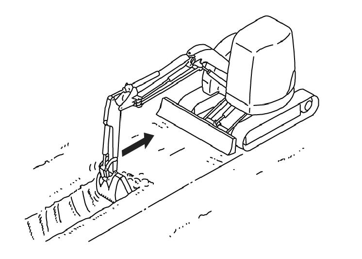
Be sure that the dozer blade is “in front.” When the operator’s cab is facing forward, the blade will be visible and travel controls will operate as expected. If the dozer blade is not visible, the operator’s cab is facing to the rear, and the travel controls will operate in reverse.
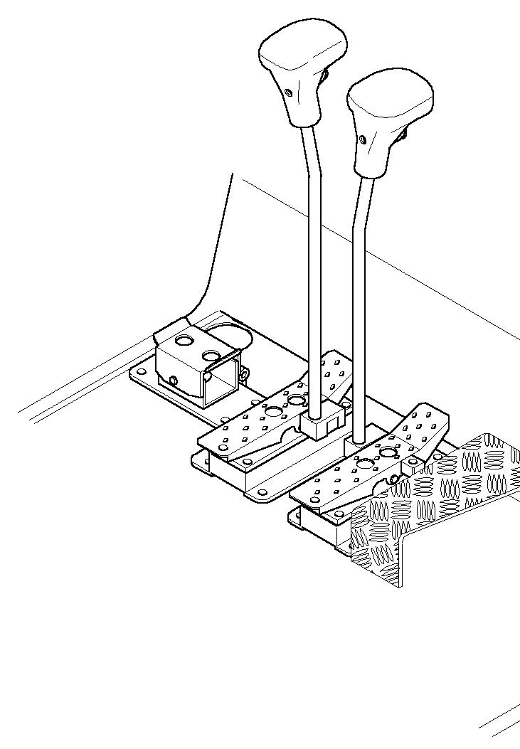
Forward Travel
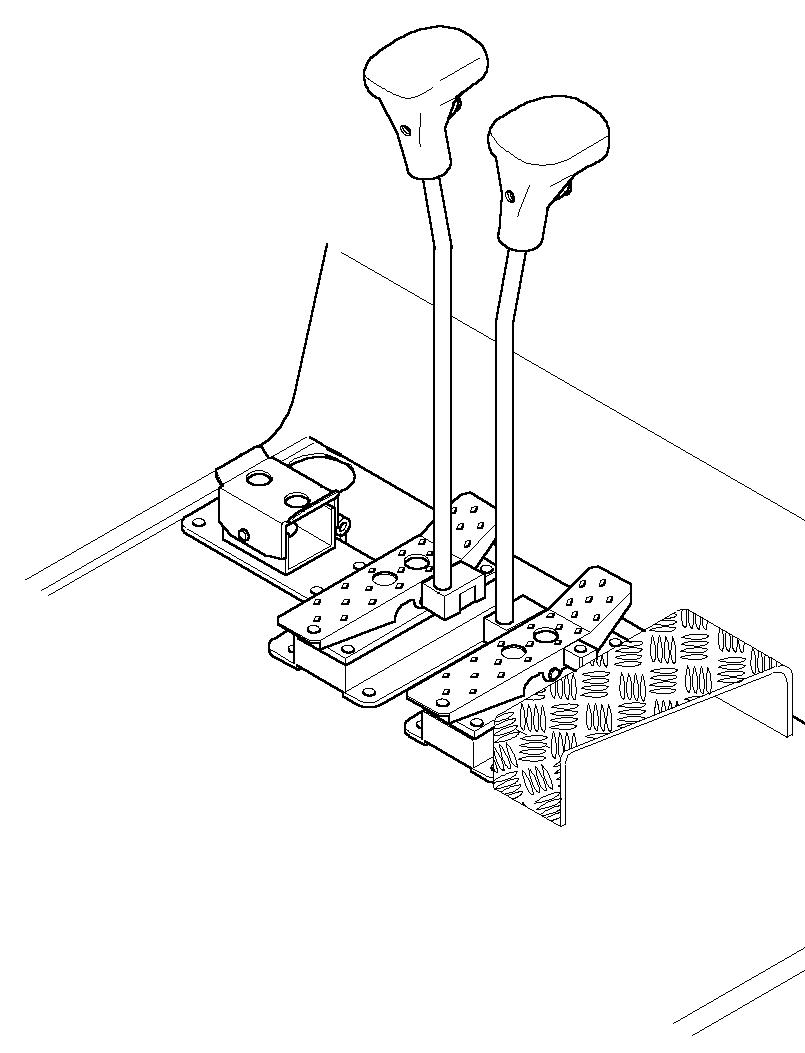
Push both travel control levers or pedals forward. The farther these are moved, the faster the machine will travel. See Figure 3-11.
Reverse Travel
Pull both travel control levers or pedals back. The farther these are moved, the faster the machine will travel. See Figure 3-11.
Turning During Travel
Move one control lever or pedal farther than the other one. To turn left while moving forward, move the right control lever farther forward; to turn right while moving forward, move the left control lever farther forward. See Figure 3-11.
Figure 3-11 Travel Controls
Spin Turn
Move the levers in opposite directions to spin the machine on its axis. To spin turn left, move the right control lever forward while pulling the left control lever to the rear; to spin turn right, move the left control lever forward while pulling the right control lever to the rear. See Figure 3-11.
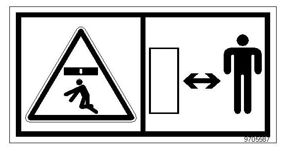
Tilting the Cab or Canopy
Warning
•Always tighten cab lock-down nuts before driving or using the machine.
•Always close the cab door before tilting the cab.
•Stay clear from underneath the cab as it is tilted.
•Always secure the tilt rod in the support position the when cab is tilted.
Refer to items 1—10 in Figure 3-12 to safely complete the following procedure.
Tilting the cab or canopy up:
1.Follow “Mandatory Safety Shutdown Procedure” on page 2-2.
2.Raise the floor mat (1) on the right, front of the cab and remove cab lock-down nut (2). Remove cab lock-down nut (3) at the right rear of the cab.
3.Securely close the cab door.
4.Locate the jack handle tubes (4) from the tool kit in the engine compartment, insert them into the jack (5) and jack to the limit. The cab will be raised as far as the jack (5) will travel.

5.Pull on handle (7) until the cab is completely tilted and supported by the safety cable (8).

6.Remove the tilt rod (9) from the storage bracket (10) and slide the tilt rod (9) into the guide bracket (11) and secure with the retention pin.
Tilting the cab or canopy down:
1.Remove the tilt rod (9) from the guide bracket (11) by removing the retention pin and slide the tilt rod (10) out of the guide bracket (9) and secure with the retention pin back in the storage bracket (10).
2.Use handle (7) to slowly lower the cab back onto the jack (5).
3.Remove jack handle tubes (4) from the jack (5) and insert the opposite end of the jack handle tubes (4) onto the release pin (6). Slowly turn release pin (6) counter-clockwise until the cab is lowered.
4.Turn the release pin (6) clockwise.
5.Reinstall the cab lock-down nuts (2) and (3).
6.Place the jack handle tubes (4) back in the tool kit.
Caution
Check tilt rod (9), the retention pin and safety cable (8) at regular intervals for cracks and cuts. Replace defective parts immediately.
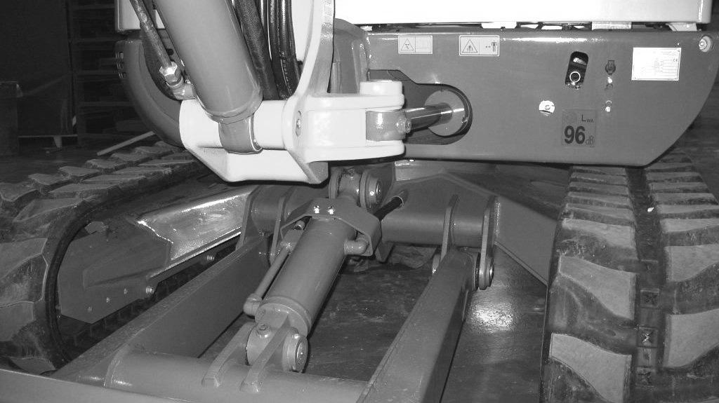
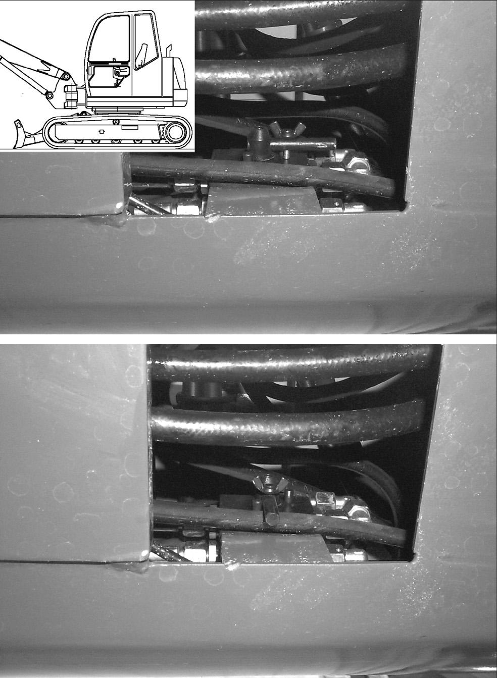
SAE/ISO Operating Controls Selector Valve
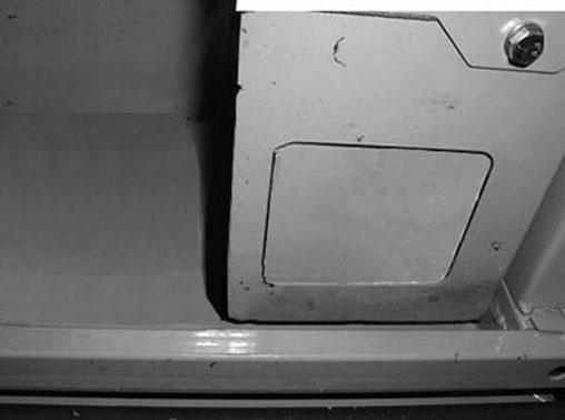
Located on the lower left side of the chassis, under the cab, is the SAE/ISO Selector Valve. See (1), Figure 313. The SAE/ISO valve can be accessed through a cutout on the left side of the chassis at location (2). This machine has been set at the factory for SAE standard operation shown at position (3). If ISO operation is desired, loosen wing nut (5) and rotate valve to position (4) and retighten wing nut (5).
SAE Operating Controls
SAE boom and bucket functions are controlled by the right and left joystick control levers located on the seat consoles.
SAE Left Joystick – see Figure 3-14.
1 – Arm extend
2 – Arm retract
3 – Swing left
4 – Swing right
ISO Operating Controls
ISO boom and bucket functions are controlled by the right and left joystick control levers located on the seat consoles.
ISO Left Joystick – see Figure 3-16.


1 – Boom lower
2 – Boom raise
3 – Swing left
4 – Swing right
5 – Boom lower
6 – Boom raise
7 – Curl bucket in
8 – Curl bucket out
5 – Arm extend
6 – Arm retract
7 – Curl bucket in
8 – Curl bucket out
Note: The joystick controls are pilot-operated. The farther the controls are moved from center, the faster the machine will function.
Note: The joystick controls are pilot-operated. The farther the controls are moved from center, the faster the machine will function.
Boom Swivel/Auxiliary Hydraulics Pedal
The boom can be swiveled without moving the swing frame by pressing and holding the auxiliary hydraulic/ changeover valve button (1) on top of the left joystick, and then pressing the auxiliary hydraulics pedal (2) left or right. See Figure 3-18. Pressing and holding the auxiliary hydraulic/changeover valve button (1) and pressing the auxiliary hydraulics pedal (2) to the left with your toe swivel the boom to the left. Pressing and holding the auxiliary hydraulic/changeover valve button (1) and pressing the auxiliary hydraulics pedal (2) to the right with your toe swivels the boom to the right.

The auxiliary hydraulics pedal (2) allows use/control of front end attachments. Action will vary depending on the attachment and how it is connected.
Dozer Blade
The dozer blade is controlled by the dozer control pedal/lever (1) located next to the travel controls. See Figure 3-19.


•Push control pedal/lever forward to lower the blade.
•Pull control pedal/lever rearward to raise the blade.
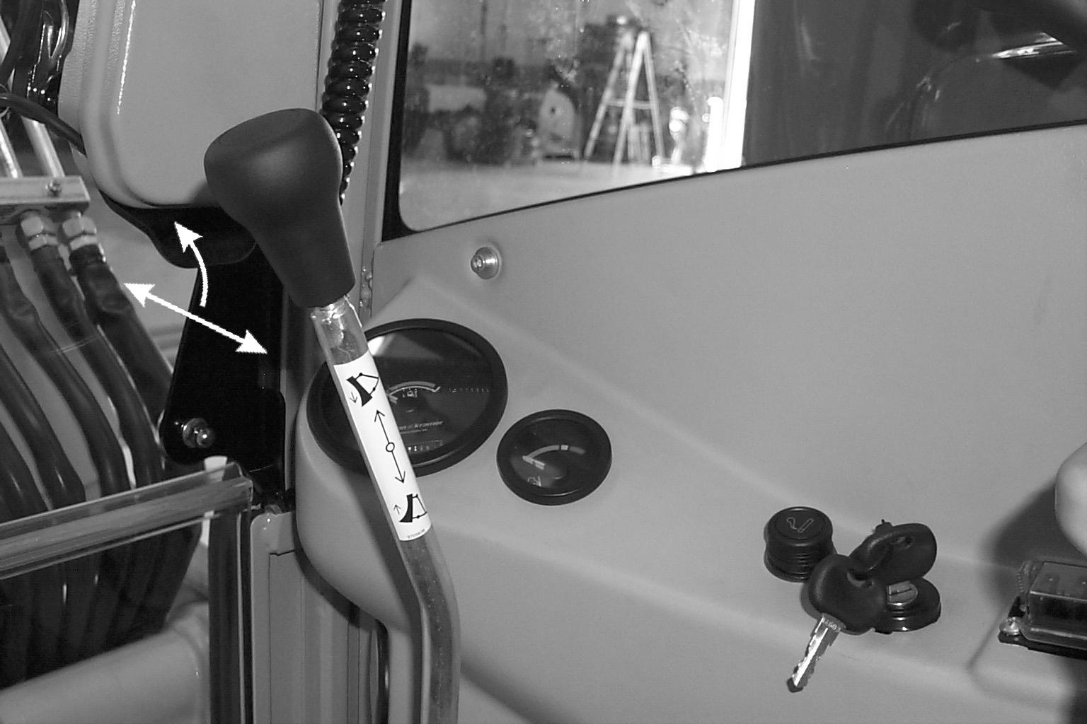
Throttle Lever

The engine speed is controlled by the throttle lever (1) In machines with serial numbers AJ02993 and up. the throttle is located behind the left armrest; in machines up to serial numbers AH02282, the throttle is located next to the right joystick. See Figure 3-20.


•Push throttle lever (1) forward to decrease engine speed.
•Pull throttle lever (1) rearward to increase engine speed.
Optional Auto-Idle Feature
Model 603 Standard; Model 503Z Option
Serial Numbers AH00645 and Up
Press switch (1) to enable the auto-idle feature. When the auto-idle feature is enabled, engine speed is automatically lowered to idle when no hydraulic functions occur for five seconds. Engine speed resumes when a hydraulic function is activated.
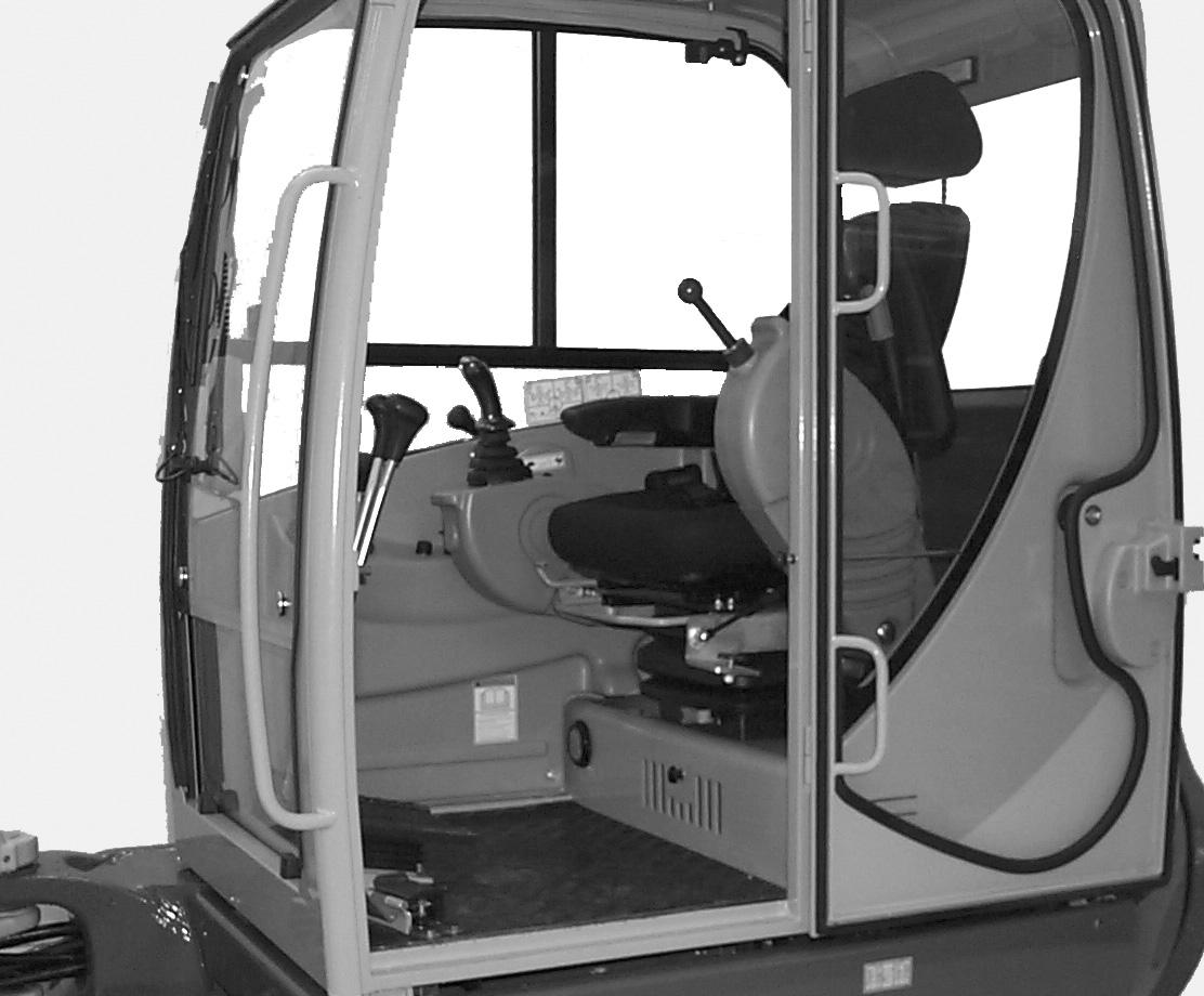
Operator’s Seat Adjustments
Note: The operator’s seat left console must be raised in order to exit the cab. In the lowered or work position, all operational functions are activated, and operator exit is blocked by the Warning Arm/Lever. In the raised position, the all hydraulic functions of the machine are locked out.
Note: Not all serial number machines are equipped with all seat adjustment options
4.Backrest Adjustment

The backrest adjustment lever (5) allows the operator to move the backrest forward and rearward.
5.Headrest Adjustment
The headrest adjustment (6) allows the operator to move the headrest up and down.
6.Seat Height Adjustment
The seat height adjustment allows the operator to move the seat height up and down. To raise the seat height, grasp the seat and lift up until you hear an audible click. To lower the seat, raise the seat to the highest position and then lower the seat to its lowest position.
7.Horizontal Suspension
When horizontal suspension is turned on, shocks from travel motion are absorbed by the seat suspension.
Arm rests
Serial Numbers AJ02993 and Up: To adjust, hold armrest (2, Figure 3-23) and pull out latch (3). Move the armrest to the desired position and release latch (3). Make sure latch (3) locks securely into a detent in the armrest.
Serial Numbers AH02282 and before: To adjust, turn the adjustment wheel (4).
Note: The rear of the left armrest has a turnbuckle that may need to be adjusted to allow the left armrest to rotate out of the way when the left console is raised. Use the turnbuckle to adjust the armrest so it does not contact the left control lever when raising the left console to the lock-out position.

Figure 3-22 Seat Adjustment – Cab Shown
1.Seat Suspension Adjustment
Rotate the knob (1) to adjust the seat suspension for the operator’s weight. An indicator on the front of the seat base shows the weight adjustment in kilograms. (1 kg = 2.2 lbs.) Adjust the seat suspension correctly to ensure a comfortable ride. See Figure 3-22.
2.Horizontal Seat Adjustment
The seat adjustment lever (2) allows the operator to move only the seat forward and rearward.
3.Horizontal Seat & Control Adjustment
The seat adjustment lever (3) allows the operator to move both the seat and the controls forward and rearward.

Seat Belt
Warning
ALWAYS fasten the seat belt securely and properly. Never operate the machine without the seat belt fastened around the operator.
Keep the seat belt clean because dirt can impair seat belt operation. Check seat belt condition regularly and have damaged or worn belts immediately repaired by an authorized workshop.
After an accident the seat belt strap is stretched and must be replaced with a new strap installed by an authorized workshop.
Make sure the seat belt is not twisted when it is fastened, and that it is fastened over the hips and not the stomach.
Fasten the seat belt tightly and securely. Remove hard, edged or fragile objects from your pockets or clothes that might lie between the seatbelt and your body.
Fastening/Unfastening the Seat Belt

Fasten the seat belt around your hips and waist and insert tab (A, Figure 3-24) into buckle (B) until it clicks securely in place. Slack in the seat belt should automatically retract into seat belt spool (D).
Unfasten the seat belt by pressing button (C).
Ventilation
Warning
Never use ether starting aids. Glow plugs are used for cold weather starting. The glow plug can cause ether or other starting fluid to detonate, causing injury.
Windshield – Optional Cab
Caution
When the windshield is opened, be sure both latches are locked. When closing the windshield, keep hands on the handles and away from path of the windshield.
The windshield can be opened for ventilation. Squeeze/ turn latches (1, Figure 3-25) located at the upper corners of the windshield. Grasp the handles (2) and pull the windshield up until the latches lock in the open position.
Serial Numbers AJ02993 and Up
The windshield can opened for ventilation. Squeeze latches (1, Figure 3-25) located at the upper corners of the windshield, pull/push the top of the windshield backwards/forward and release latches. Pull/push the top of the window until the catch locks the top of the windshield securely in place.
To close the windshield, squeeze/turn the latches and then lower the windshield. Lock the latches in the closed position.
Caution
Support the windshield when releasing it from the ceiling catches to avoid possible head injury.
For additional ventilation, the lower portion of the windshield can be removed and securely stored in the glass holder (3) located on the rear window.
Before closing the windshield, first re-install (if removed) and lower the bottom windshield (See “Movable Bottom Window – Optional Cab” on page3-22). Close the windshield by squeezing/turning the latches, and then lower the windshield and lock the latches in the closed position.
Side Window – Optional Cab
Squeeze button (1, Figure 3-26) and slide the window to open. Release button (1) when the window is in the desired position. Make sure the window lock securely in one of the recesses.
Movable Bottom Window – Optional Cab

Serial Numbers AJ02993 and Up
Squeeze both latches (1, Figure 3-27) on the left and right and slide the window at both latches to open or close. Release latches and make sure the window locks securely open/closed.


Note: If the lower front window is raised all the way into the windshield frame, it will move with the windshield as a unit if the windshield is raised for ventilation.
Serial Numbers up to AH02282
The lower front window can be removed and securely stored in the glass holder (3, Figure 3-25) located on the rear window.

Important
Re-install the lower window before lowering the windshield.
Cab Door Latch Release – Optional Cab
When fully opened, the left cab door will lock in position to the side of the cab. To release the latch, use the black knob (1) located on the inside of the door. See Figure 3-28.
Model503Z/603--SerialNumbersAH02282andearlier shown--laterserialnumberssimilar
Latch Release
Interior Light
The interior light is located on the back of the cab above the rear window. Press the switch to the right or left to turn the light ON. Move the switch to the center position to turn the light OFF.

Tool Kit and Cab Jack Handle
The machine tool kit and the cab jack handle are located in the storage area under the hood in the engine compartment.
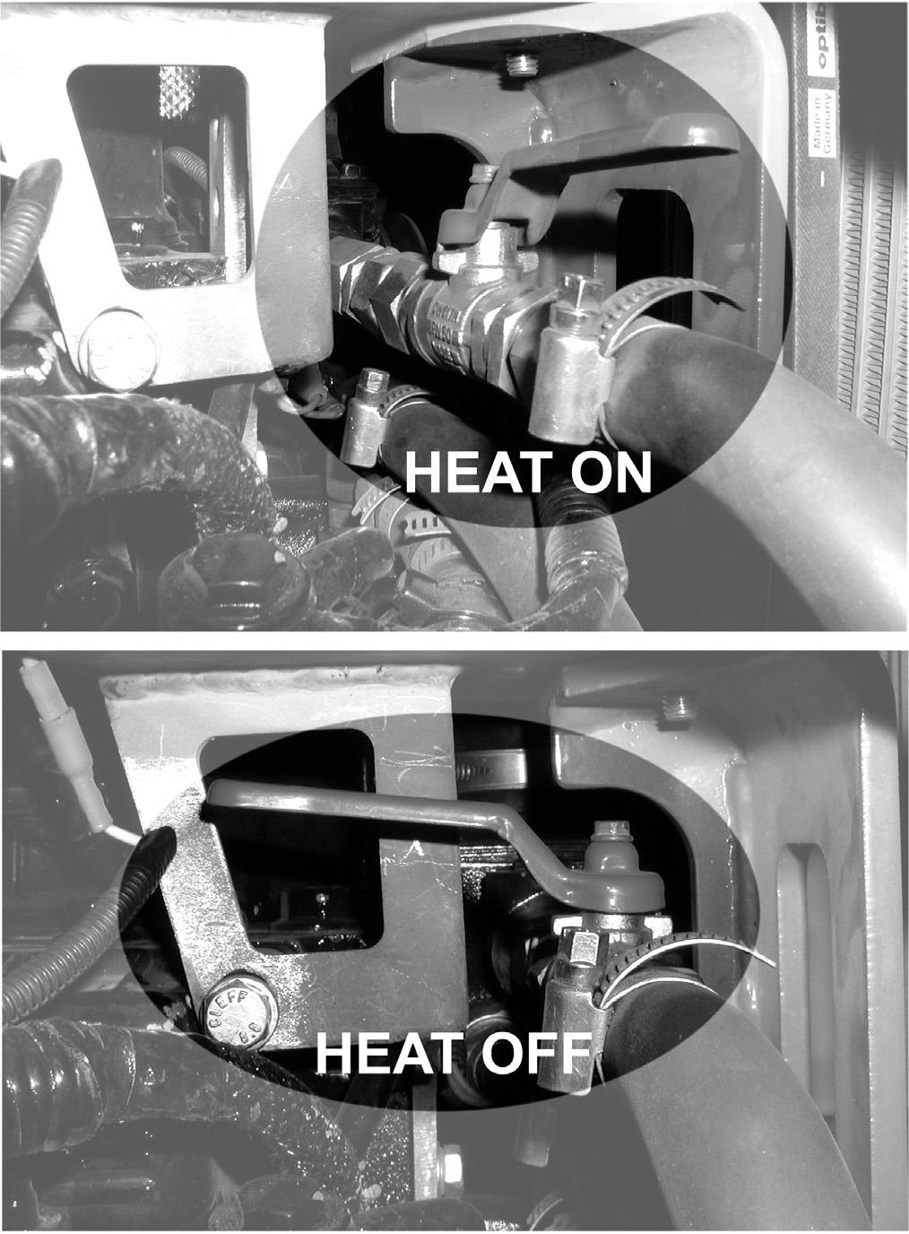
Cab Heat Control – Optional Cab
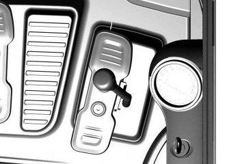
During the colder months, the operator’s cab heater can be turned on by rotating the dial near the vent (Figure 3-30). On older models, turn on the cab heater by opening the heater valve located under the hood on top of the engine behind the radiator (Figure 3-31). Rotate the lever to either the “heat on” or “heat off” position as required.
Note: The recirculated air mode vent is a storage compartment on the canopy model machines.
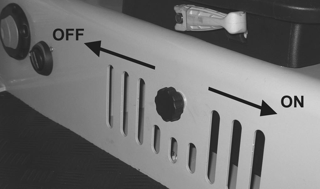

Recirculated Air Mode
When heating or cooling the cab, the recirculated air mode can be utilized to heat or cool only the air in the cab with no fresh air supply from the outside. Sliding the plate to the left will turn ON the recirculated air mode by closing the vent. Sliding the plate to the right will turn OFF the recirculated air mode by opening the vent. Figure 3-32 shows the unit with recirculated air mode turned OFF.
Preheated Fresh Air
Selection of “cold” or “preheated” fresh air in winter.
Mounting/Removing Buckets
ALWAYS wear protective goggles, helmets, gloves, steel-toed shoes, etc.
DO NOT service the bucket while the engine is running.
DO NOT stand behind the bucket when removing the pins.
DO NOT use your hands or fingers to align the bucket and dipper arm holes.
ALWAYS verify the bucket is safely locked before starting the engine and resuming operation.
Warning
Figure 3-33 Fresh Air
A deflector plate on the heater baffle can be set to two different positions:
•Fresh air-heater takes in air from outside the cab. See Figure 3-33.
•Preheated fresh air-heater takes in air from the chassis. See Figure 3-34.
•DO NOT use a hammer directly on a securing pin to loosen it. The pounding may cause splintering, which may lead to serious injury.
•The bucket can crush hands or feet. DO NOT use your hands or feet as substitutes for the correct equipment.
Removing A Bucket
1.Lower the bucket to the ground with the flat side facing down (1, Figure 3-35).
Important
Place the bucket against the ground with minimum pressure. More pressure increases resistance, which will make it more difficult to remove the pins.
Figure 3-34 Preheated Fresh Air
Change from fresh air to preheated fresh air as follows:
•Tilt the cab. See “Tilting the cab or canopy” on page 3-15. The deflector plate is located on the heater under the cab.

•Loosen both attachment screws.
•Reposition and fit the deflector plate back on again.
•Tilt the cab back down again and secure it.
2.Stop the engine.
3.Remove the two lynch pins (2A and 2B, Figure 335).
4.Remove the lower securing pin first (3B, Figure 335) and then the other (3A). Carefully remove the pins with a hammer and brass punch if they are stuck. Once pin 3B is removed, pin 3A might have more pressure applied against it, making it difficult to remove. If this happens: a.Start the engine. b.Slightly raise and lower the boom to relieve pressure from the pin. c.Turn off the engine. d.Try removing the pin again, using a hammer and brass punch if needed.
Attaching A Bucket
1.Grease the dipper arm and bucket holes.
2.Since the bucket is on the ground and stationary, maneuver the machine until the dipper arm holes align flush with the bucket holes.
Warning
DO NOT use your hands or fingers to align the bucket and dipper arm holes.
3.Stop the engine.
4.Insert the upper securing pin first (3A, Figure 335). If needed, use a hammer and brass punch to gently tap the pin through the hole. Insert a lynch pin (2A, Figure 3-35) through the hole in the pin and lock.
Important
The flat side of each securing pin head must align with the flat guide on each side of the hole; see 3A and 3B in Figure 3-27 for how the pins look when properly installed.
5.Insert the lower securing pin (3B, Figure 3-35). If needed, use a hammer and brass punch to gently tap the pin through the hole. Insert a lynch pin (2B, Figure 3-35) through the hole in the pin. Lock the lynch pin securely in place.
6.Verify the bucket is locked and secure before starting the engine and resuming operation.
Auxiliary Hydraulics Connections
Important
Follow the instructions in the operator’s manual from the attachment manufacturer for connecting the attachment to the machine’s auxiliary hydraulics machine’s auxiliary hydraulics.
7.To connect each coupling: a.If necessary, rotate lock sleeve (2, Figure 3-37) so notch (3) aligns with lock ball (4). b.Pull lock sleeve (2) down in the direction of arrow (5). c.Insert the attachment coupling into the corresponding auxiliary hydraulics connection coupling.
Figure 3-36 shows the three quick connections on the dipper arm meant for auxiliary hydraulics, which are for the following:
• 1: Pressure line (male connector)
• 2: Large return line (female connector)
• 3: Pressure line (female connector) d.Release lock sleeve (2) so it snaps into place and locks the couplings together. Verify the lock sleeve (2) is snapped closed and the coupling is securely locked together. e.Twist lock sleeve (2) so notch (3) is NOT aligned with lock ball (4), to help prevent accidental de-coupling.
Disconnecting the Quick Couplings
1.Perform steps 1 through 6 in “Connecting the Quick Couplings” on page3-27 before proceeding to the next step.
2.To disconnect each coupling: a.Pull lock sleeve (2, Figure 3-37) down in the direction of arrow (5). b.Listen for the hissing sound to verify that any pressure has been released from the connection. c.Twist lock sleeve (2) so notch (3) is aligned with lock ball (4).
3-36 Auxiliary Hydraulics Connections
Connecting the Quick Couplings d.Push lock sleeve (2) up in the direction of arrow (6) to disconnect the coupling.
1.Park the machine on firm and level ground.
2.Extend the dipper arm cylinder halfway and position the boom/dipper arm so the auxiliary hydraulic connectors are positioned as shown in Figure 3-36.
3.Stop the engine.
4.Turn the ignition key to position 1.
5.Release pressure from the bucket cylinder by moving the left control lever to the left and right.
6.Lift the left control lever base as a safety precaution.
Machine Operation
Warning
•Read and understand this entire manual. Follow warnings and instructions for operation and maintenance. Failure to follow instructions can result in injury or death.
•Read and understand all safety decals before operating the machine. DO NOT operate the machine unless all factory installed guards and shields are in place.
•Be sure you are familiar with all safety devices and controls before operating the machine.
•Know how to stop the machine before starting.
•Use only with approved accessories or referral attachments. Manitou Americas, Inc. cannot be responsible for safety if the unit is used with nonapproved attachments..
•Check for correct function after adjustments or maintenance.
Pre-Operation Checklist
Important
See the list of recommended lubricants in “Fluid Capacities/Lubricants” on page1-4 for proper grade of engine oil and hydraulic oil. Only use oils specified on the list. specified on the list.
Check the following items at the beginning of each work day or every 12 working hours:
•Seat belt and mounting hardware
•Safety decals (replace as required) (page 2-10)
•Air cleaner and intake hoses (page 4-10)
•Engine coolant level and system for leaks (page 414)
•Clean engine area of any flammable materials.
•Engine oil level (fill as required) (page 4-9)
•Hydraulic system for leaks
•Hydraulic oil level (fill as required) (page 4-9)
•Pivot points for proper operation
•Track tension and condition (page 4-23)
•Windshield washer reservoir level (cab machines only) (page 4-26)
•Lights, signals, indicators warning lights and indicator lights
•Attachment safely locked onto machine and attachment condition
•V-belt condition and tension (page 4-22)
•Lubrication points lubricated
•Broken and loose parts (repair as required)
•Engine cover securely latched
•Fuel level (page 4-11)
Important
Do not run the engine until the fuel tank is completely empty. If this happens, air will enter the fuel system, and the fuel system will have to be bled. Always fill the tank with fuel at the end of the working day. with fuel at the end of the working day.
Warning
Never use ether starting aids. Glow plugs are used for cold weather starting. The glow plug can cause ether or other starting fluid to detonate, causing injury.
Engine Start and Stop
Note: When all machine controls are stationary (no pilot control pressure), the swing motor and travel motor brakes are automatically applied. When any control is activated, the appropriate brake is automatically released.
Note: All hydraulic functions are locked out with the operator’s seat left console in the raised position.
Engine Start Procedure
Danger
DO NOT run the engine in an enclosed area without proper ventilation. Be sure there is adequate fresh air if running the machine in an enclosed area.
Warning
Ensure that bystanders are a safe distance away from the machine before starting the engine.
1.Adjust the operator’s seat to desired settings.
2.Fasten the seat belt.
3.Be sure all levers and controls are in the neutral positions.
4.Make sure no one is dangerously close to the machine.
5.Insert the ignition key into the switch and turn it clockwise to the (II) position. Indicators for oil pressure and battery voltage should light. In cold weather, the glow plug indicator will come on while the glow plugs warm the engine.
6.Turn the key fully clockwise and hold it until the engine starts, and then release the key.
Note: The key must be returned to the (I) position between attempts to start the engine in order to activate the glow plug system.
Important
Do not activate the starter motor for longer than 20 seconds during each starting attempt. If the engine does not start, turn the key fully counter-clockwise, wait 30 seconds, and then attempt to start the engine again.
Important
Indicator lamps should go out when the engine starts. If they do not, turn the engine off IMMEDIATELY. Do not use machine until the problem has been identified and repaired.
7.Allow engine to warm up at idle speed for approximately 10 - 15 minutes to fully warm up all systems.
8.Test the drive pedals and control levers and check for proper operations before working with the machine.
Cold Weather Engine Starting Procedure
Note: Install an in-block or tank style engine heater that will keep engine block and oil warm for easier cold weather starting.
Note: Be sure engine oil is correct type and viscosity for the ambient (air) temperature.
Note: Be sure battery is fully charged.
1.Follow all steps under “Engine Start Procedure” above.
2.Advance the throttle to 1/4 engine speed for a faster warm up.
3.As the engine warms up, move the throttle lever to the idle position.
After Starting/During Operation
Check the following after startup and during operation. Stop the engine and fix problems before continuing operation.
1.Warning indicator lights on?
2.Travel drive/steering operating properly?
3.Boom, dipper, cab rotation and bucket controls operating properly?
4.Engine exhaust excessively smoky?
Engine Shut Down
Mandatory Safety Shutdown Procedure
Before leaving the machine:
1.Bring the machine to a complete stop on a level surface. Avoid parking on an incline or a hillside, but if this is not possible, park across the slope.
2.Lower the working equipment to the ground and support it securely.
3.Run the engine at idle speed for a few minutes to allow systems to cool after operation at full speed.
4.Turn the key fully counter-clockwise to shut off the engine. Wait for all movement to stop.
5.Move the joysticks in all directions to verify the hydraulic system is de-pressurized.
6.Lock-out controls by raising left control console.
7.Remove the ignition key and take it with you. Exit the machine using the hand-holds.
New Machine Break-in Procedure
A new machine requires reduced operational speed during the first 50 operating hours to properly break in various parts. If the machine is subjected to hard use during the break-in period, damage to operating systems may occur.
Perform the following when operating a new machine:
•Perform all steps in “Pre-Operation Checklist” on page3-28.
•Start engine and let it idle for 10 - 15 minutes so all components and systems can warm up.
•Operate machine at about 80% of maximum loads and speed.
•At the end of the first 100 operational hours, drain and replace the engine oil and engine oil filter.
Travel WARNING
•Before operating the travel levers, be sure that you know in which direction the machine is pointing. If the dozer blade is not visible from the operator’s cab, you are looking at the rear of the machine and the travel controls will be the reverse of normal operation.
•Before moving, be sure that there are no personnel in the way of the machine. Sound the horn to alert workers that you are about to move the machine.
•Be sure the path is clear during travel.
•Use extreme caution when reversing travel. Be sure there is a clear path behind the machine.
•Operate the travel control levers smoothly to avoid sudden starts and stops.
•Before leaving the operator’s seat, be sure to lock out all control systems and shut down the engine to avoid accidental activation.
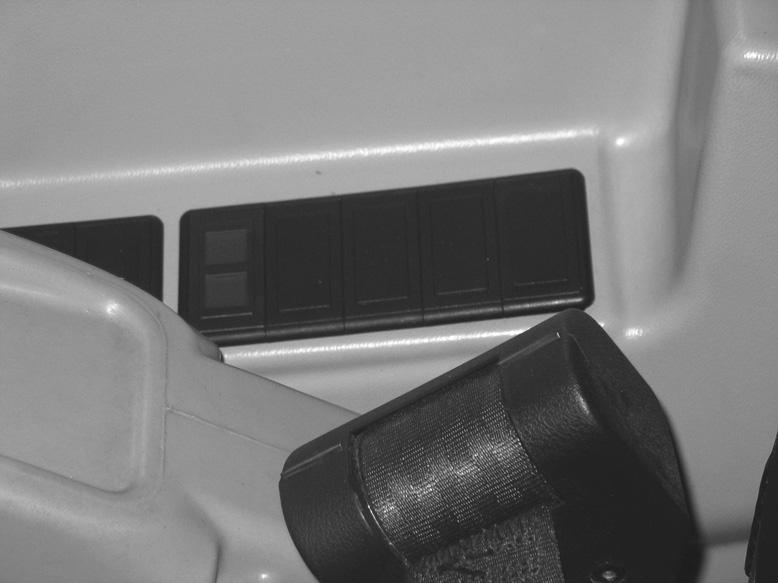
Travel Speed Selection
Two travel speed ranges can be selected by using the Travel Speed Switch (1) located on the control console. See Figure 3-38. The 503Z and 603 units use an Auto2-Speed transmission on the drive motors. This feature enables the transmission to automatically switch from high to low speed when it senses a load.
Travel speeds are:
•Slow Speed Maximum = 1.7 mph (2.8 km/h)
•High Speed Maximum = 2.9 mph (4.7 km/h)
Caution
The slow-speed setting should be selected to prevent automatic up-shifts if conditions warrant.
3.Travel straight up and down slopes; never travel across the slope. See Figure 3-39. Extend arm and lower boom to keep the bucket about 12” (300 mm) off the ground. If the machine starts to slide or becomes unstable, lower the bucket to regain control. If the engine stalls, lower the bucket, make sure that all controls are in the neutral position and restart the engine. See “Operating on Slopes” on page3-33 for more information about operating the machine on slopes.

Figure 3-39 Travel Down Slopes
4.To travel straight, push both travel control levers (or pedals) forward (or rearward). The farther the levers (or pedals) are moved, the faster the travel speed.
5.Pivot (or wide) turns are made by rotating only one track forward (or rearward). The machine will pivot on the stationary track.
6.Spin turns are made by rotating one track forward and one track rear. The machine will spin around its mid-point.
7.The excavator can travel in water that comes up to the top of the upper track rollers. Be sure that the footing is solid so that the machine will not sink.
Figure 3-38 Travel Speed Selection
General Travel Instructions
1.Avoid sudden movements and sharp turns.
2.Travel slowly on rough, frozen, or uneven terrain.
Machine Operation
Joystick Controls
Extending and retracting the cylinders (boom, arm and bucket) are controlled by the joysticks located on the consoles attached to the operator’s seat. See page 3-17 for control configurations.
Note: The joystick controls are pilot-operated. The farther the controls are moved from center, the faster the machine will function.
Hydraulic Swivel Unit Brake
Swing frame rotation is sufficiently braked by moving the control lever back to the initial position. Moving the control lever in the opposite direction brakes the swing frame with full hydraulic pressure.
Important
Hydraulic swivel unit brake function is not optimal if the hydraulic system has not reached operating temperature.
The upper carriage’s rotation is sufficiently braked by moving the control lever back to the initial position. Moving the control lever in the opposite direction brakes the upper carriage with full hydraulic pressure.
Mechanical Stop Brake
A multi-disc brake integrated into the rotation drive has an additional mechanical brake effect with a time delay. This brake is used to stop the swivel unit from rotating in any position.
Operating Precautions
Danger
•DO NOT elevate the front end of the tracks by use of downward pressure on the dozer blade. This will cause the machine to become unstable.
•DO NOT excavate underneath the machine.
•Always be sure that there is adequate support underneath the machine. Be aware of conditions that could cause the earth or foundation to collapse, resulting in risk of injury or death.
•Do not position the machine directly underneath structures during demolition. Falling objects or structure collapse could cause severe damage or personal injury.
•Be sure that there is the proper clearance from overhead electrical lines.
•Be sure that all underground electrical power and gas supply lines are clearly marked and avoided.
Warning
•DO NOT rest your feet on the travel pedals during normal machine operation. Unexpected machine movement could occur.
•On Model 603 machines, make sure there are no obstacles in the immediate area before rotating the swing frame because the rear section of the swing frame protrudes over the undercarriage.
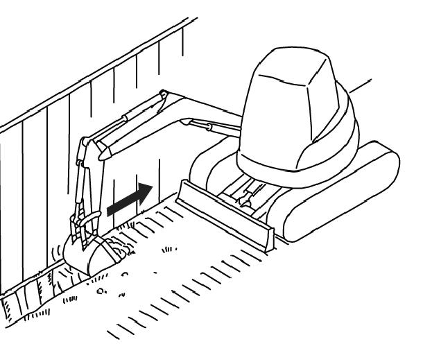
•When working close to an excavated edge, be sure that the ground the machine is sitting on is solid. Keep the travel motors to the rear. See Figure 3-40.
DO NOT use machine travel or swing to provide additional breakout force when the bucket is in the ground.
DO NOT jam bucket into the ground and use machine weight to provide additional breakout force.
When working on soft or muddy ground, be sure that the machine is not sinking.
DO NOT use the bucket as a hammer or ramming device.
Important
When digging at maximum excavation depth, BE SURE that the dozer blade does not contact the boom cylinder. Damage to the boom cylinder may occur if it contacts the dozer blade.
Warning
•Do not travel up or across a slope steeper than 15°. Do not travel down a slope steeper than 25°. Keep boom centered while traveling.
•Keep attachments as low as possible when traveling on slopes or rough terrain.
Operating on a slope is hazardous. It is recommended to level the work area as shown in Figure 3-41. If this is not possible, use the following guidelines:
•Travel straight up and down slopes; never travel across the slope. See Figure 3-39. Extend arm and lower boom to keep the bucket about 12” (305 mm) off the ground. If the machine starts to slide or becomes unstable, lower the bucket to regain control. If the engine stalls, lower the bucket, be sure that all controls are in the neutral position and restart the engine.


•When traveling down a slope, put the machine in the position shown in Figure 3-42, control the speed with the travel levers and the throttle controls, and reduce engine RPM.
•To achieve the best stability while excavating, lower the dozer blade to the ground.
•Operate as slowly as possible and avoid sudden changes in direction.
•Avoid traveling over objects such as rocks, trees, stumps, etc.
•Stop the machine travel before moving the bucket or dozer controls.
•Slow the work cycle. Take your time.
•Avoid working with the tracks positioned across the slope. Position the machine with the blade downhill and lowered.
•Avoid swinging or extending the bucket farther than necessary in a downhill direction. If you must swing the bucket downhill, keep the boom low and skid the bucket along the ground.
•When working with the bucket on the uphill side, keep the bucket as close to the ground as possible. Unload far enough away from the excavation to prevent the possibility of a cave-in.
Cold Weather Operation
In cold weather, mud should be removed from the machine before parking. See “Track Cleaning” on page4-23 for cleaning mud off of the tracks. If possible, park the machine on solid ground, or on wood planks, to prevent the track or undercarriage from freezing to the ground.
Operating in Water
Do not operate or immerse the machine in water higher than the top of the upper track rollers.
Thoroughly grease the machine if it has been operated in deep water.
Swiveling the Boom
Warning
Working with the boom swiveled to the side reduces lifting capacity.
Overloading the bucket can cause an unstable condition and increases the possibility of tipping the machine.
The excavator boom can be swiveled from the front position 61º to the right and 65º to the left on the 503Z, and 51º to the right and 75º to the left on the 603. This allows excavation of trenches along walls, fences, etc. See Figure 3-43.

Figure 3-43 Boom Swivel Control
Press and hold the auxiliary control button, located on top of the left joystick. Then press the auxiliary hydraulics pedal (2, Figure 3-43) with your toe or heel. Pressing the pedal down to the left swivels the boom to the left. Pressing the pedal down to the right swivels the boom to the right.
Bucket controls do not change when swiveling the boom.
Grading
Bulldozing
Warning
•Be sure there is proper clearance for the front end attachments when bulldozing.
•Be sure that the front end attachments do not contact any overhead power lines or obstructions during bulldozing.
•DO NOT drive machine into the excavation or onto loose soil, which can cause an unstable condition, and possible tipping of the machine.
1.Raise or lower the dozer blade using the control lever/pedal located to the right of the travel levers/ pedals. See Figure 3-44. Move the control forward to lower the dozer blade, rearward to raise the dozer blade.
2.The boom must be fully raised and the bucket curled in (up) when grading.
3.When grading, the material may be pushed away to the front or the side.
4.Raise the dozer blade slightly if excessive resistance occurs.
5.When the blade is in position, use the travel controls to move the machine as in normal travel.

Excavation
The following section applies to an excavator with a standard bucket, which is used mainly for digging into the ground to loosen, excavate and load loose or solid material.
Important
Never use the excavator bucket to perform actions other than digging, grading, loading and excavating. Damage to the excavator could result.
•Do not use the swiveling force of the excavator so the bucket serves as a hammer or battering ram (1, Figure 345).


•Do not lower the bucket into the ground while rotating the upper carriage or driving the excavator (2, Figure 3-46).
•Do not use the falling force of the dipper arm so the bucket serves as a hammer or pile-driver (3).
•Do not cause the excavator to tip, bounce or fall to amplify digging or excavating (4) force.
•Use caution when retracting the bucket to prepare for driving or transport. Hitting the bucket into the dozer blade might damage either attachment, especially the bucket teeth.
•The dozer blade is intended for grading only; using it as a battering ram risks serious damage to the blade, its cylinder and connections.
•When excavating, lower the dozer blade to the ground to aid machine stability. Whenever possible, it is best to position the dozer blade on the same side as the excavation.
•Do not support the weight of the machine on one side of the dozer blade.
Excavating
Proper Bucket Position
Move the flat side of the bucket so it is parallel to the ground (Figure 3-47).
Important
Positions 2 and 3 in Figure 3-47 show improper bucket orientations while excavating.

Position 2 forces the bucket downward into the ground, slowing down work and subjecting the engine and hydraulic pump to overloading.
Position 3 forces the bucket upward toward the ground surface, reducing productivity because of reduced bucket loads.
4.After the bucket is sufficiently filled: a.Continue moving the dipper arm toward the excavator. b.Extend the dipper arm cylinder so the bucket is tilted upward (6, Figure 3-48). c.Raise the boom.
Proper Digging Technique
1.Lower the bucket into the ground (4, Figure 3-48).
2.After the bucket penetrates the ground, adjust it so its flat side is parallel to the ground (5, Figure 348).

3.Pull the bucket towards the excavator by: a.Moving the dipper arm toward the excavator, and b.Lowering the boom.
Trench Excavating
Trench excavating is most efficient when the machine tracks are parallel to the line of the trench (Figure 349). For larger trenches, excavate each side first and then the center.
When excavating in confined areas, excavate by rotating the upper carriage and swiveling the boom (Figure 3-50).
Warning
Placing the dozer blade on the opposite side of the excavation decreases machine stability. Always consider operator safety when operating the machine, especially under less-than-ideal working conditions.
Loading Vehicles
When loading vehicles, consider the following:
•Whenever loading in a confined area with a limited range of motion, position the truck so maximum visibility is ensured for the excavator operator.
•Working alongside trenches and deep excavation are two applications where the dozer blade might restrict bucket movement. When working alongside trenches, lower and place the dozer blade on the ground to avoid damage to the boom cylinder. When deep excavating, position the machine so the lowered dozer blade is on the opposite side of the excavation (Figure 3-51).

•When work conditions permit, position the truck so the excavator can load material at the rear of the truck instead of the sides (1, Figure 3-52). The most effective way to load into the rear of the truck is when the truck and excavator form a 45° angle (2, Figure 3-52).

•Raise the boom and dipper arm to dump height just before rotating toward the truck.
•Whenever possible, dump upwind to keep dust and airborne debris away from the operator, and the excavator air filters and fans.
Transporting Towing
Warning
•When towing the machine, make sure no one is close to the towing apparatus, or in between the vehicles. The machine may only be towed using suitable towing equipment, in connection with suitable towing apparatus, such as a towing coupling, hooks and eyes.
•Do not use a towing apparatus that is kinked, twisted, or otherwise damaged.
•Do not apply high loads abruptly to the retrieval apparatus. The towing bracket has a maximum admissible load of 6992 lbf (3110 daN).
•The towing bracket is designed for retrieving the machine only. Do not use the excavator to tow other vehicles.
•Do not tow the machine if the travel drive is damaged. Damage to the machine cause by towing is not covered under warranty.
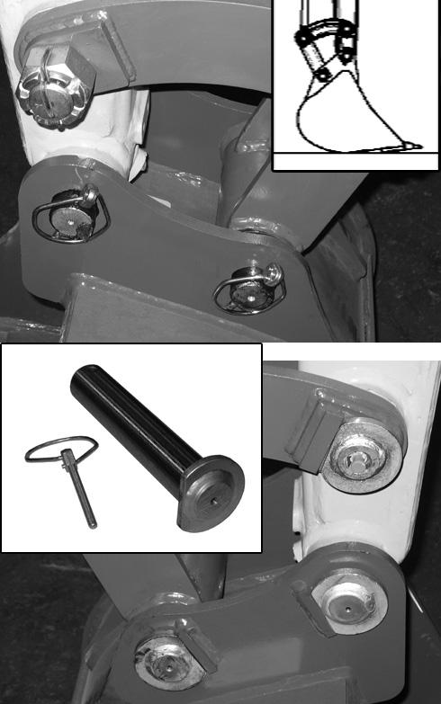
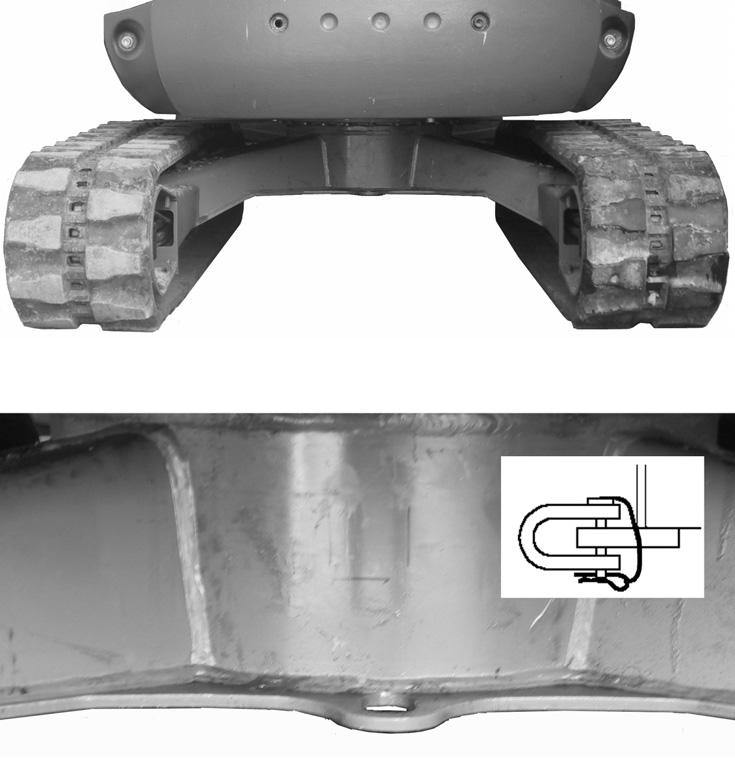
The Excavator can be towed by using the towing bracket (1). Secure a towing shackle, shackle pin and lock (2) of adequate size to the towing bracket (1) as shown in Figure 3-53. Tow the machine slowly and only short distances.
Lifting the Machine
Warning
•Use a lifting device and rigging with sufficient capacity for the weight of the machine plus any attachments
•While lifting, maintain the center-ofgravity and balance points on the machine. See Figure 3-54.
•Do not swing the boom.
•Never lift the machine with the anyone on-board.
Secure the lifting fixture sling to the lifting points (1) as shown.
• Model 503Z: length L1 on the lifting sling for the boom must be 5’, 7” (1.70 m) long; length L2 on the lifting sling must be 12’, 11” (3.93 m) long. See Figure 3-54.

• Model 603: length L1 on the lifting sling for the boom must be 6’, 7” (2.0 m) long; length L2 on the lifting sling must be 15’, 0” (4.6 m) long. See Figure 3-54.
•Do not exceed rated load capacity of the lifting machine. See “503Z General Specifications” on page1-9 and “603 General Specifications” on page1-10 for excavator weights.
Loading and Transporting
Use only transport machines that are in proper working order and are approved for use on public roads.
Warning
•Do not exceed the transport vehicle’s gross weight rating and the gross axle weight rating when loading and transporting the machine.
•The transport vehicle must have sufficient capacity for the size and weight of the machine. See “503Z General Specifications” on page1-9 and “603 General Specifications” on page1-10.
•Make sure the load does not fall short of the minimum axle load of the steering axle of the transport vehicle, otherwise the transport vehicle’s steering could be seriously affected.
•Adjust transport speed to the load, to the road/traffic conditions and to the handling of the transport vehicle. Consider all possible transport conditions such as: heavy braking, evasive maneuvers, and uneven or rough roadways.
When using ramps to load the machine:
•Do not exceed an incline of 17° (30%). See Figure 3-55.
•Clean dirt, mud, ice and snow from the ramps and tracks.
•Use metal loading ramps with a slip-resistant surface, and with beveled ends to prevent damage to rubber tracks.
1.Attach ramps securely to the transport machine to prevent them from slipping off during loading.
2.Load the machine on solid, even ground.
3.Apply the transport machine parking brake and chock the wheels.
4.Determine the direction of the track movement (dozer blade facing forward) before moving the machine onto the ramps.
5.Raise the bucket and dozer blade on the excavator high enough so they will not touch the ramps during loading.
6.Slowly and carefully drive the machine onto the transport vehicle. Do not change direction while driving on the ramps. Instead, drive down off of the ramps, and re-align the machine with the ramps.
7.After the machine is on the transport machine, lower the dozer blade and the bucket onto the loading surface and turn of the engine. See Figure 3-55.
8.Perform the Mandatory Safety Shutdown Procedure on page 2-2.
9.Lock the cab. Do not allow anyone to stay in the machine.
10.Place chocks under the machine tracks and secure the machine to prevent slipping, overturning and moving on the transport machine.
11.Use the tie down points (1) identified by decals for securing to the transport machine. See Figure 3-55. Securely tie the excavator to the transport vehicle at the front, rear and the sides.

Secure the machine properly so it cannot slip, slide, roll, tip over or fall, or cause the transport vehicle to tip over under transport conditions. Use anti-slip bases and linings, load-securing straps and chains, clamping beams, protective paddings, nets, edge protectors, etc. as needed to properly secure the load. Consider all possible transport conditions such as: heavy braking, evasive maneuvers, and uneven or rough roadways. Make sure the load does not exceed the authorized maximum height.
Optional Controls
Proportional Auxiliary Hydraulic Joystick Control (Option)

The proportional auxiliary hydraulic joystick control enables the following new functions:
•Selectable two-speed variable auxiliary hydraulic mode at startup (precision or power).
•Auxiliary hydraulic control moved to the right joystick thumb control.
•Auxiliary hammer operation is enabled for the right joystick trigger button control.
Note: With proportional auxiliary hydraulic joystick control, the auxiliary hydraulic / changeover valve button (A, Figure 3-56) is not functional. Pedal (B) always controls boom swivel and does not change to control the auxiliary hydraulics if button (A) is pressed. The auxiliary hydraulics are instead controlled using the thumb and trigger switches installed on the new right joystick.
Two-Speed Variable Auxiliary Hydraulic Mode Selection
Upon startup, the auxiliary hydraulic system can be placed into either the power mode, or the precision mode. Select the appropriate mode depending upon the job requirements.
1.Shut down the excavator.
2.To set the auxiliary hydraulics to power mode, slide and hold the thumb switch (C, Figure 3-57) on the right joystick to the right and start the excavator.
3.To set the auxiliary hydraulics to precision mode, slide and hold the thumb switch (C, Figure 3-57) on the right joystick to the left and start the excavator.
4.Continue holding thumb switch (C) until the proportional control indicator (D, Figure 3-58) flashes. It will flash once when starting in precision mode; twice when starting in power mode.
Note: After the excavator is started, it must be shut down and restarted in order to change between auxiliary hydraulic modes.
AuxiliaryHydraulicsProportional JoystickControl
When the excavator is running, use the thumb switch (C, Figure 3-59) on the right joystick to control the auxiliary hydraulics.
Auxiliary Hydraulic Hammer Operation
Note: Use the power mode (refer to “Two-Speed Variable Auxiliary Hydraulic Mode Selection”) when operating a hydraulic hammer attachment. Maximum performance of hammer attachments is only possible using the power mode.
To operate an auxiliary hydraulic hammer attachment, press and hold trigger button (D, Figure 3-60) on the right joystick. The hammer will operate continuously until button (D) is released.