10 minute read
CHAPTER 10 PREPARING FOR FIELD OPERATION

Tractor Requirements
The tractor, to be used to operate a Disc Conditioner, MUST have:
1.A minimum of 85 hp (64 kW)
2.A 1000 RPM PTO matching the operating speed of the Disc Conditioner.
3.PTO and hitch dimensions as shown.
4.Two remote hydraulic outputs capable of powering a double-acting cylinder. A minimum operating pressure of 1800 PSI (12400 kPa) is required to lift the Disc Conditioner.
5.It is recommended that the towing tractor be equipped with an enclosed operator’s cab with safety glass or polycarbonate windows, or with protective mesh screens.
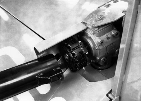
IMPORTANT: If this unit is connected to a tractor equipped with a clevis style drawbar, the clevis parts shown in dashed lines MUST be removed to prevent damage to the unit Driveline. See Fig. 39.
Attachment To Tractor
IMPORTANT: Whenever the Conditioner is operated on a tractor other than the original tractor the Conditioner was set up for, the Drawbar Height and Header Flotation must be checked and adjusted accordingly.
Tractor Drawbar Requirements, 3-Point Hitch (After Serial Number 12100)(Fig. 40)
Adjust the tractor hitch to meet Dimension 5 in Figure 40. Position the drawbar left or right of center. Also adjust the tractor hitch turnbuckles so that the distance between universal cross centers on the tractor to implement PTO is between 23 to 33 inches (585 to 838 mm) throughout the full range of tractor hitch motion.
IMPORTANT: DO NOT exceed the listed dimensions, or damage to the tractor and Disc Mower Conditioner will occur.
Hitch Positions (Fig. 41)
The Disc Mower Conditioner Hitch can be set up to fit category II and category III 3-point and quick hitches. The Disc Mower Conditioner Hitch mounting width is changed by exchanging the Hitch Brackets mounting positions. Hitch Pin diameters are changed by adding or removing Hitch Bushings. Hitch Bushings are stored in the Toolbox when not in use.
NOTE: The bolt pattern in the Hitch and Hitch Brackets is such that the Hitch Brackets MUST be switched side-to-side, and not turned over. The Hitch Bracket is properly installed when the flared flanges face downwards.

Tractor Drawbar Requirements, Clevis Hitch (After Serial Number 12100) (Fig. 42)
Adjust the tractor drawbar to meet Dimension 3 in Figure 42 to avoid damage to the front Telescoping PTO
Drive. Adjust the drawbar left or right to place the hitch pin hole directly in line with the PTO Shaft.
IMPORTANT: To prevent damage to the Disc Conditioner Telescoping Drive, PTO Tower and Tractor PTO Shaft, avoid making sharp turns.
1 – Tractor PTO Shaft (Tractor MUST comply with ASAE Standard S203).
2 – 6″ to 12″ (152 to 305 mm) [8″ (203 mm) preferred] This is measured from the center of the traactor PTO shaft to the top of the tractor drawbar at the hitch pin hole.
3 – 17″ (432 mm) for 1000 RPM operation. This is measured from the retaining groove in the Tractor PTO Shaft to the center of the Hitch Pin.
4 – 34-1/2″ (845 mm) for 1000 RPM operation. This is measured from the retaining groove in the Implement Input Drive Shaft to the center of the Implement Hitch Hole.
5 – 13″ to 22″ (330 to 560 mm) [18″ to 20″ (457 to 508 mm) preferred] This is measured from the top of the tractor drawbar at the hitch pin hole to level ground.
6 – 0″ to 3″ (0 to 76 mm) Tire Bumper Extension Kit NOT required; 3″ to 6″ (76 to 152 mm) optional Tire Bumper Extension Kit required (see Optional Equipment and Accessories chapter of this manual), 6″ and above, DO NOT use tractor with this hitch as driveline damage will occur.
Tractor Drawbar Requirements (Before Serial Number 12101)
(Fig. 43)
Adjust the tractor drawbar to meet Dimension 2 in Figure 43 to avoid damage to the front Telescoping PTO
Drive. Adjust the drawbar left or right to place the hitch pin hole directly in line with the PTO Shaft.
IMPORTANT: To prevent damage to the Disc Conditioner Telescoping Drive, PTO Tower and Tractor PTO Shaft, avoid making sharp turns.
1 – Tractor PTO Shaft (Tractor MUST comply with ASAE Standard S203).
2 – 17″ (432 mm) for 1000 RPM operation. This is measured from the retaining groove in the Tractor PTO Shaft to the center of the Tractor Hitch Pin Hole.
3 – 25″ (635 mm) for 1000 RPM operation. This is measured from the retaining groove in the Tractor PTO Shaft to the center of the Hitch Extension Pin.
Quick Attach Drawbar Extension (Before serial Number 12101)
The Quick Attach Hitch Extension can be adjusted to fit tractor drawbars 1-1/8 to 1-3/4″ (29 to 44 mm) thick and 2 to 3-7/16″ (51 to 88 mm) wide. Spacers of 1-1/4″ , 1-3/8″,1-1/2″ and 1-5/8″ are also provided to reduce the hitch pin hole. The Hitch Extension MUST be adjusted to fit the tractor drawbar before use and MUST be readjusted when connecting to a tractor with a different size drawbar. Unless otherwise directed, refer to Fig. 44 for the following steps:
4 – 34-1/2″ (845 mm) for 1000 RPM operation. This is measured from the retaining groove in the Implement Input Drive Shaft to the center of the Implement Hitch Hole.
5 – Measure distance from the center of the Tractor PTO Shaft to level ground.
6 – Measure distance from the center of Implement Input Drive Shaft to level ground. (Disc Mower must be attached to Tractor and be lowered to mowing position). Dimension 6 should be within 2″ (51 mm) of Dimension 5.
7 – Implement Input Drive Shaft.
1.Set the tractor drawbar to specifications shown in Fig. 43.
2.Select the largest Spacer that fits inside the tractor drawbar hitch pin hole.
NOTE: The Spacer is stored on the Drawbar Extension Hitch Pin when the Drawbar Extension is removed from the tractor.
3.Unlock and pull out the Hitch Pin.
4.Remove and retain the 1/2″ Cap Screw and Lock Washer.
5.Adjust 3/4″ Cap Screws to clear tractor drawbar.
6.With the Hitch Extension placed loosely on the tractor drawbar, determine the maximum amount of Shims that can be placed in the Hitch Box. Remove the Hitch Extension from the tractor drawbar. Align the Shims with the Hitch Pin and secure with the retained 1/2″ Cap Screw and Lock Washer.
7.Install the Quick Attach Hitch Extension Assembly by placing the Spacer inside the tractor drawbar hitch pin hole, sliding the Assembly on the tractor drawbar. Secure by inserting the Hitch Pin through the Hitch Box, the Spacer and tractor drawbar, and lock with the Hitch Pin Lock provided.
8.Adjust all 3/4″ Cap Screws against the tractor drawbar to center the Hitch Box on the drawbar within 1/16″ (2 mm). Tighten the 3/4″ Jam Nuts on one side. Loosen the two Cap Screws on the opposite side just enough (less than 1/2 turn) to allow the Hitch to slide on the tractor drawbar, then tighten the two Jam Nuts.
9.Store extra Shims, Spacers and Instruction Card in the plastic Box provided. Proceed to the Conditioner Tongue Hitch Plate installation topic.
IMPORTANT: If the available mounting positions do NOT permit the Driveline to be level, position the Drive to be as level as possible with the Header in mowing position.
Conditioner Tongue Hitch Plate (Before serial Number 12101) (Fig. 45)
IMPORTANT: If the tractor is equipped with a 3-point hitch, raise the lower arms to their maximum height (or remove them) to avoid interference with the Telescoping Drive and PTO Tower on the Disc Conditioner. Failure to do so will result in significant damage to the unit.
The Drawbar Extension and Hitch Plate should be attached to the tractor drawbar and end of the Disc Conditioner Drawbar (Tongue) in such a manner as to make the front Telescoping Drive Shaft as level as possible, when Header is resting on the ground. MAKE SURE to follow the measurement information as shown in Figure 43.
1.Raise Disc Conditioner tongue to clear the Hitch Pin and back tractor to align Hitch Pin with hole in Hitch Ball on Tongue. Lower Tongue to rest on Hitch Pin. Install Hitch Pin Lock in Hitch Pin to secure.
After the connection is made, remove the Hitchjack and secure it to the “Storage Hub” on the left side of the Tongue.
PTO
Clean and lightly grease the splines on the tractor PTO shaft and the Yoke of the Telescoping Drive. Depress the Safety Lock Ring and slide the Yoke onto the tractor PTO shaft. Move the Yoke back and forth until the Safety Lock Ring pops forward and locks into the groove in the PTO shaft.
Warning
BE SURE that the PTO safety lock ring is positively engaged and that the tongue is securely connected to the tractor 3-point hitch with the supplied locking pins, to the tractor drawbar with a locking clip pin, or to the tractor drawbar hitch extension with a locking clip pin BEFORE starting the tractor engine. Also, BE SURE that the tractor PTO shield is in place and properly secured and that the telescoping drive shields rotate freely BEFORE starting the tractor engine.
Hydraulic Lift
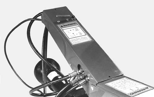
Install the supplied quick-disconnect fitting (to match your tractor connection) onto the Lift Cylinder Hose (left Hose). Make the Lift Cylinder Hose attachment to the tractor, start the tractor and operate the valve to raise and lower the Disc Conditioner several times to purge the air out of the system.
IMPORTANT: If the Disc Mower Conditioner is NOT horizontal when it is being raised and lowered, refer to the Service chapter for corrective measures.
STEERING AND LIFT CYLINDER HOOKUP (Fig. 46)
The two hoses (2 right Hoses) from the Steering cylinder should be hooked up so that when the tractor Control Handle is moved to the forward position the Header will move to the right. (Pressure from this line will retract the Steering Cylinder). Moving the Control Handle to the rearward position will move the Header to the left. (Pressure on this line will extend the Steering Cylinder.) The Lift Cylinder Hose should be connected to another valve so when the Control Handle is pulled to rear position the entire machine will raise. The operator may prefer to position the Cylinder connections differently for more efficient use of the Control Handles during field operation.
Warning
Do NOT remove hydraulic tongue control cylinder with conditioner header off the ground. Failure to heed can result in death or serious injury.
NOTE: Operation of the Tongue Control Cylinder requires a tractor with two remote hydraulic outputs, one for the Tongue Control and another for the Lift Control.
CUTTING HEIGHT & HEADER FLOTATION
Adjust the Cutting Height and Header Flotation following information in the Adjustments chapter of this Manual.
SAFETY CHAIN (Fig. 47)
Only a Safety Chain (NOT an elastic or nylon/plastic tow strap) should be used to retain the connection between the towing and towed machines, in the event of separation of the primary attaching system. Refer to Optional Equipment & Accessories chapter for part number information.

BREAK-IN
Before starting to cut and condition, it is recommended that the Disc Mower Conditioner be broken-in by running it empty for approximately 20 minutes. This initial run-in should be done with the Header on the ground. Before running the unit however, perform the daily (10 hour) maintenance routines listed in the beginning of the Operation chapter.
The Break-in should consist of a five minute and a fifteen minute running period. First, run the unit for five minutes with the tractor engine close to idle RPM. Next, stop the unit and exercise the MANDATORY SAFETY SHUTDOWN PROCEDURE (page 8). Reinspect the unit. After inspection is complete, connect the PTO, start the tractor, engage the PTO near engine idle speed and gradually increase the speed to proper operating RPM and continue running the machine for 15 minutes. Stop the unit and exercise the MANDATORY SAFETY SHUTDOWN PROCEDURE (page 8) again. After another inspection, the Disc Mower Conditioner is ready for the field.
IMPORTANT: The oil in the Cutterbar and the Gearboxes MUST be changed after the first 10 hours of operation. For details, see the Lubrication chapter of this manual.
Transporting
BEFORE transporting the Disc Mower Conditioner, refer to the Transporting chapter of this manual for additional transporting information.
Chapter 11 Transporting
TRANSPORT LOCKS (Figs. 48, 49 & 50)
When the Disc Mower Conditioner is going to be transported on a public highway, BE SURE to raise the unit all the way up and install both Lift system Transport Locks. Also, BE SURE to swing the Drawbar to the centered Transport position with the Hydraulic Hitch Positioner and position the Transport Lock Valve on the Drawbar in the Transport (“closed”) position.
SAFETY CHAIN (Fig. 51)
Warning
ALWAYS follow state and local regulations, regarding a safety chain (NOT an elastic or nylon/plastic tow strap) when towing farm equipment on public highways! A safety chain should always be used to retain the connection between the towing and towed machine, in the event of separation of the primary attaching system. BE SURE to check with local law enforcement agencies for the particular regulations. NEVER transport the disc mower conditioner at speeds greater than 20 mph (32 km/h).
On units not equipped with the 2-Point Hitch, the Disc Mower Conditioner can be equipped with a safety chain for operation on public highways. A sturdy Chain Loop is welded to the side of the Drawbar to facilitate anchoring the Chain. The safety chain, when attached in this manner, has the following characteristics:


1.Chain is sufficiently slack to allow turns and movements of either the tractor or the farm implement, without placing tension on the Chain.
2.Chain is of sufficient strength to hold the decoupled implement (and its load) and tow it to the shoulder.
TRANSPORT LIGHTS (Fig. 53)
Transport Lights are provided as standard equipment on the Disc Mower Conditioner. The Lights use a standard 7-pin connector to connect to the tractor. If your tractor is not equipped with the proper receptacle, see your tractor dealer for details.
SMV EMBLEM AND REFLECTORS (Figs. 54 & 55)
The Disc Mower Conditioner is provided with a Slow Moving Vehicle Emblem Mounting Bracket on the upper left back end of the Conditioner Frame. A Slow-moving Vehicle Emblem, is standard after Serial Number 10700.

Red, Orange and Amber Reflector Strips are also provided at the rear corners of the Conditioner Frame.
1 – Red Reflectors (2 Places)
2 – Amber Reflectors (6 Places)
3 – Orange Reflectors (2 Places)
4 – SMV Emblem & Bracket (Standard Equipment)
Fig. 54: SMV & Reflectors (After Serial Number 12100)
1 – Red Reflectors (2 Places)
2 – Amber Reflectors (6 Places)
3 – Orange Reflectors (2 Places)
4 – SMV Emblem & Bracket (Standard Equipment)
Fig. 55: SMV & Reflectors (Before Serial Number 12101 and After Serial Number 10700)