3 minute read
CHAPTER 1 INTRODUCTION


Your decision to purchase this piece of GEHL equipment was a good one. We are sure that your decision was carefully considered and that you are looking forward to many years of work from this machine. We, as a Company, have invested much time and effort in developing our lines of equipment. The equipment you have purchased is built with a great deal of pride, and designed to give you long life, efficient operation, durability and dependability.
This manual was developed specifically for the machine you have purchased. The information within is for your assistance in preparing, adjusting, maintaining and servicing your machine. More importantly, this manual provides an operating plan for safe and proper use of your machine. Major points of safe operation are detailed in the SAFETY chapter of this manual. Refer to the Table of Contents for an outline (by chapters) of this manual. Use the Index, located at the back of this manual, for specific chapter and topic/page number references.
This GEHL equipment is provided with a Pocket, on the back side of the Tool Box located behind the Shield on the right side of the Header, for storing the Operator’s Manual. After using it, please return the Manual to the Pocket and keep it with the unit at all times! Furthermore, we recommend that if this machine is re-sold, this Manual accompany the unit.
Modern machinery has become more sophisticated and, with that in mind, GEHL Company asks that you read and understand the contents of this manual COMPLETELY and become familiar with your new machine, BEFORE attempting to operate it.
Our wide Dealership network stands by to provide you with any assistance you may require, including genuine GEHL service parts. All parts should be obtained from or ordered through your GEHL Dealer. Give complete information about the part and include the model and serial numbers of your machine. Record the serial number in the space provided on the pictorial, as a handy record for quick reference.
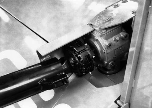
The Disc Conditioner model and serial numbers are on a plate located on the left side of the Main Frame. “Right” and “Left” are determined from a position standing behind the Disc Conditioner, facing the direction of travel.
Standard hardware torques appear in a chart at the end of the manual.
GEHL Company reserves the right to make changes or improvements in the design or construction of any part without incurring the obligation to install such changes on any unit previously delivered.
Throughout this manual, information is provided which is set in italic type and introduced by the word NOTE or IMPORTANT. BE SURE to read carefully and comply with the message or directive given. Following this information will improve your operating or maintenance efficiency, help you to avoid costly breakdowns or unnecessary damage and extend your machine’s life.
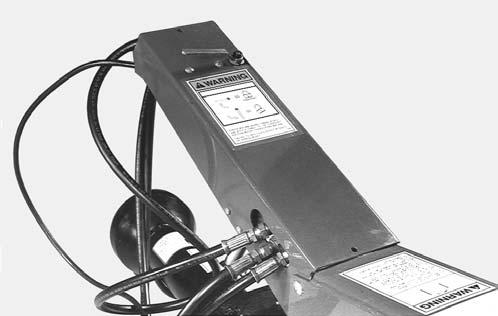
The GEHL Company, in cooperation with the American Society of Agricultural Engineers and the Society of Automotive Engineers, has adopted this SAFETY ALERT SYMBOL to pinpoint characteristics which, if not properly followed, can create a safety hazard. When you see this symbol in this manual or on the unit itself, you are reminded to BE ALERT! Your personal safety is involved.
Chapter 2 Specifications
All Dimensions are in Inches (Millimeters) Unless Otherwise Noted
Model and DescriptionDC2412 Disc Mower . . . . . . . Conditioner
Number of Discs9
Total Number of Knives18 . . . . . . . . . . . . . . . . . . . . .
Cutting Width138-1/2 (3518)
Overall LengthApprox. 273 (6934) . . . . . . . . . . . . . .
Operating HeightApprox. 56 (1422)
Transport Width141 (3581) . . . . . . . . . . . . . . . . . . . .
Minimum Power Required85 hp (64 kW)
TiresTwo 31 x 13.5 x 15, . . . . . . . . . . . . . . . . . . . . . . . inflated to 30 psi (210 kPa)
Weight (Approximate)5100 lb (2320 kg)
Conditioner Roller Diameter9.5 (241) . . . . . . . . . . . .
Conditioner Roller Length111 (2819)
Conditioner Roller Speed765 rpm
Cutting Height1-1/4 to 3-1/4 (32 to 83) . . . . . . . . . . . up to 5-1/4 (133) with Optional Tall Skid Shoes
Disc Speed3000 rpm
Knife
Speed181 mph (292
Disc Angle0° to 6° down
Cutterbar5 U.S. Pints (2.35 L)
. . . .
Swivel Hitch – Top Gearbox37 oz (1.1 L) (After SN12100)
Swivel Hitch – Bottom Gearbox56 oz (1.7 L) (After SN12100)
Standard Features:
1000 RPM Drive Line
Overrunning Slip Clutch-protected Telescoping PTO Drive Line
Reversible Twisted Cutting Knives
Replaceable Skid Shoes to Regulate Cutting Height with the Use of Hydraulic Disc Angle Adjustment
Dual Hydraulic Cylinder Lift System
Hydraulic Swing Cylinder for Tongue Positioning
Adjustable Deflectors for Windrow or Swath Forming
Transport Lights
Intermeshing Rubber Rollers
Quick Attach Drawbar Extension (Before SN12101)
SMV Emblem & Mounting Bracket (After SN10700)
Optional Features (Customer Selected):
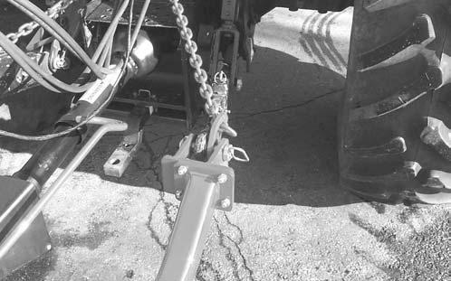
2-Point or Drawbar Style Hitch (After SN12100)
Safety Chain
Tall Skid Shoes
V-Blades
Crop Lifters
Wide Tire Bumper Extension Kit