
7 minute read
SERVICE MACHINE SAFETY

from Frontier Sickle Bar SB 3106 SB 3107 SB 31078 Operator’s Parts Catalog Manual(GH19502990) - PDF DOWNL

Attention
It is absolutely essential to disengage the tractor pto, lower the mowing machine, switch off the tractor, ensure that this is at a complete standstill and remove the key before servicing, adjusting or preparing the implement for work. All assembly operations must be carried out on a work bench.
• Always keep oils and greases well away from children’s reach.
• Always thoroughly read the warnings and precautions indicated on the containers.
• Avoid contact with the skin.
• Always thoroughly and fully wash after use.
• The utilized oils should be treated in compliance with the current laws in force.
•Do not proceed with maintenance and cleaning if the power take-off has not been disconnected first, the engine power off, the hand brake pulled and the tractor blocked with a wooden block or stone of the right size under the wheels.
•Periodically check that the bolts and nuts are tight, and if necessary tighten them again. For this it would be advisable to use a torque wrench, respecting the values of 52 Nm for M10 bolts, resistance class 8.8, and 143 Nm for M14 bolts resistance class 8.8 (Table 1: Bolts tightening torques).
•During assembling, maintenance, cleaning, fitting, etc., with the mowing machine raised, place adequate supports under the equipment as a precaution.
•The spare parts must correspond to the manufacturer’s specifications. Use only original spares .
Bolts tightening torques - settings given in Nm (lb-ft)
Lubrication
WARNING:• Firmly block sickle bar on horizontal surface.
• Always keep oils and greases well away from children’s reach.
• Always thoroughly read the warnings and precautions indicated on the containers. Avoid contact with the skin.
• Always thoroughly and fully wash after use. The utilized oils should be treated in compliance with the current anti-pollution laws.
Routine maintenance
•During the first working hours, check that the screws are tight (Fig. 56).
Every 8 work hours
•Grease points (A and B, Fig. 44).
•Grease the PTO shaft and its telescoping parts.
•Adjust belt tension periodically by adjusting nut (A, Fig. 45). Check tension via the viewing panel on the belt guard. Belt slack must not exceed 1 inch. It is essential to close the inspection hatch with the relative lid after the belts have been examined.
Every 50 work hours
•Check the tightness of the connecting rod bolts regularly (Fig. 46).
•Checking the clearance tolerance.
Periodically (6 months)
•Grease point (A and B, Fig. 44).

After each mowing job
• Clean and oil the mowing bar blades according to the instructions in the chapter entitled: "Cleaning and oiling the cutters" .
Lubricants
•It is advisable to use SAE 85W/140 OIL or equivalent for the reduction unit (or gear box) and side transmission.
•It is advisable to use GR MU EP 2 GREASE or equivalent for all greasing points.
Cleaning and oiling the cutters
Danger
Mowing bar cleaning and oiling are very dangerous operations. Always comply with the following instructions:
•Switch off the tractor, remove the starter key and disengage the pto;
•Brake the tractor and make sure it is unable to move;
•Lift the implement by means of the lift links in a flat place where it cannot slip;
•Operate the mowing bar, checking that there are no persons or animals in the vicinity;
• Wash the mowing bar with a jet of pressurized water, standing at least 5 feet away from the implement ;
•Check the condition of the cutters;
• When the mowing bar is dry, oil the cutters with very viscous oil;
•Operate the mowing bar for a few seconds, checking that there are no persons or animals in the vicinity;
•Switch off the tractor, remove the starter key and disengage the pto;
•Fit the guards over the cutters and outer skid (C, Fig. 47).
Checking the clearance tolerance
Attention
It is absolutely essential to disengage the tractor pto, lower the mowing machine, switch off the tractor, ensure that this is at a complete standstill and remove the key before servicing, adjusting the implement for work. All assembly operations must be carried out on a work bench.
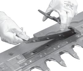
Every 50 hours of operation, the clearance between the tooth and upper blade guide must be checked. Too much clearance allows material to enter the cutting blade, leading to the possible breakage of the various parts of the cutting blade, as well as compromising cutting quality. Too little clearance creates excessive sliding friction on the blade as it slides, leading to the possible breaking of the tooth holding bar, the blade head or parts of the hinge. The check is to run between the tooth and the upper blade guide. The optimal clearance is determined by the passing of a shim (Fig. 48). If a shim cannot pass between the tooth and upper blade guide, a shim must be added (Fig. 51). If, on the other hand, two coupled shim can pass (Fig. 49), a shim must be removed in order to restore optimal clearance conditions.
ONE SHIM (GH 13011510)
TWO SHIMS (GH 13011510)
To restore the correct tolerance:
•unscrew the blade guide (Fig. 50);
•remove one or more shims (Fig. 51);
•put the blade guide back in the same position.
IMPORTANT: When replacing the teeth or the toothholding bar, carry out the check described above. When required, put back the shims to avoid striping or damage.
Storage
It is advisable to proceed in the following way at the end of the season or if the machine is to remain inactive for a long period of time:
•Treat the implement in compliance with the instructions given in the chapter entitled: "Cleaning and oiling the cutters".
•Carefully check for any damaged or worn parts and replace these as necessary.
•Fully torque all screws and bolts.
•Apply a little lubricant to the unpainted parts.
•Protect the entire implement with a cover.
•Lastly, store the implement in a dry place where it cannot be tampered with by unauthorized persons; the mowing machine must be set-up on flat and compact ground, supported by the relative supports (F and G, Fig. 52).
Careful compliance with these instructions will be all to the advantage of the user who will be sure to use an implement in perfect conditions when work begins again. G
Attention
It is absolutely essential to disengage the tractor pto, lower the mowing machine, switch off the tractor, ensure that this is at a complete standstill and remove the key before servicing, adjusting the implement for work. All assembly operations must be carried out on a work bench.
Replacement of section-holding bar (L, fig. 55)
•With the implement resting on the ground, open the mowing bar.
•Remove the expansion pin (H, Fig. 53) and pull out the section-holding bar (Fig. 54) with the hooking tie rod (I, Fig. 54).
•Insert the new section-holding bar and lock it in place with the expansion pin. Lubricate the cutters with very viscous oil during the assembly phase.
Replacement of sections (J, fig. 55)
•With the implement resting on the ground, open the cutter bar.
•Remove the expansion pin (H, Fig. 53) and slide out the section-holding bar (Fig. 54), (7, Fig. 4 on page 6).
•Remove the damaged section using a pin punch.
•Rivet a new section with the rivets provided (J, Fig. 55).
•Insert the section-holding bar and lock it in place with the expansion pin.
Attention
It is absolutely essential to disengage the tractor pto, lower the mowing machine, switch off the tractor, ensure that this is at a complete standstill and remove the key before servicing, adjusting the implement for work. All assembly operations must be carried out on a work bench.
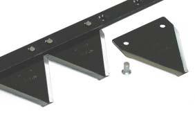
Replacement of bar holding removable tooth
•With the implement resting on the ground, raise the mowing bar and secure it with the hooking tie rod.
•Unscrew all the tooth fastening screws (Fig. 56).
•Remove all the teeth (Fig. 57).
•Remove the expansion pin and slide out the bar.
•Insert the new tooth-holding bar and lock it in place with the expansion pin.
•Reposition the teeth and fasten them with the screws.
Replacement of removable tooth
•With the implement resting on the ground, raise the mowing bar and secure it with the hooking tie rod.
•Unscrew the screws of the tooth to be replaced (Fig. 56).
•Slide out the tooth (Fig. 57), put in the new one and lock it in place with the screws. For this it would be advisable to use a torque wrench, respecting the values of 30 Nm.
Replacement of belts
•Unscrew the screws (M, Fig. 58) and remove the protective casing.
•Loosen the belt tensioner completely (N, Fig. 58).
•Replace the worn belts with new ones.
•Put these at the optimum tension using the belt tensioner. Belt play should not exceed 1 inch.
•Put the protective casing back in position and fix it in place with the screws (M, Fig. 58).
Replacement of pulleys
Notes for replacement of pulleys, if necessary.
•Unscrew the screws (M, Fig. 58) and remove the protective casing.
•Loosen the belt tensioner completely (N, Fig. 58).
•Remove the belts.
To replace the driving pulley (O, Fig. 59), turn it clockwise; viceversa, turn the driven pulley (P, Fig. 59) counterclockwise.
Demolition And Disposal
Demolition and disposal
This operation is to be carried out by the customer. Before demolishing the machine, you are advised to carefully check its physical condition and ascertain whether there are any parts of the structure that may be susceptible to structural collapse or breakage during demolition.
The customer should operate in compliance with the environment protection laws in force in his/her country.
Caution
The machine demolition operations should be carried out by skilled personnel only, equipped with suitable protective clothing (safety footwear and gloves) and auxiliary tools and equipment. All the disassembly operations for demolition should be carried out with the machine stopped and detached from the tractor.
Before demolishing the machine, you are advised to render harmless all the parts that may be a source of danger and therefore:
•scrap the structure using specialized firms, •remove any electrical apparatus according to the laws in force, •collect oils and greases separately, to be disposed of through specialized firms, in accordance with the regulations of the country in which the machine was used.
When the machine is demolished the identification label must be destroyed together with this manual.
Foreword
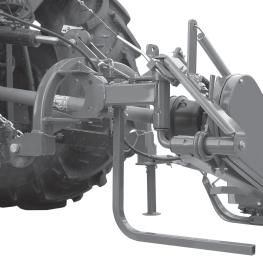
This chapter describes the phases involved in assembling a crated mower. When handling and assembling the unit, and subsequently during use and maintenance, always use suitable personal protection devices (A): always wear suitable clothing and the indicated protections. See the operating manual supplied with the unit for indication of the symbols used in this manual. When handling the unit, lift it by hooking up the special attachments and using a suitable hoist or crane rated for the weight of the unit. This operation is quite dangerous and must only be performed by prepared, responsible personnel. The machine weight is indicated on the identification label. The hook-up points are identified by the "hook" symbol (B). When moving the unit, make certain that all protections and safety devices are in place.
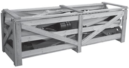
Dimensions and weight
Sickle bar components


Do not tighten securing nut (A) on the moving guide completely: allow for proper movement of the guide. 11.0