
9 minute read
MACHINE SAFETY LABELS AND POSITIONS

from Frontier Sickle Bar SB 3106 SB 3107 SB 31078 Operator’s Parts Catalog Manual(GH19502990) - PDF DOWNL

1. Keep all shields in place.
2. Disengage and shut off all engine and/or motor power before servicing or unclogging machine.
3. Keep hands, feet and clothing away from power-driven parts.

8 9
Preparing the tractor
CAUTION: Avoid injury. Proper ballastings is required for safe operation of your sickle bar
IMPORTANT: Refer to the tractor operator manual for proper ballasting information and tire inflation
•A 540 rpm PTO
•Refer to the tractor operator is manual for correct ballasting and tire pressure, depending on installed equipment.
Park vehicle safety
•Stop vehicle on a lever surface, not on a slope.
•Disengage PTO.
•Engage the park brake.
•STOP the engine.
•Remove the key.
•Before you leave the operator’s seat, wait for engine and all moving parts to STOP.
Stay clear of rotating drivelines
Entanglement in rotating driveline can cause serious injury or death:
•Wear close fitting clothing.
•STOP the engine and be sure PTO driveline is stopped before getting near it.
Installing sickle bar on tactor
The sickle bar can be hitched to , or quick coupler category tractor equipped with a universal three-point coupling.
Danger
Application of any implement to a tractor is a very dangerous operation and must only be carried out with the utmost care in compliance with the instructions.
The correct tractor/sickle bar position is established by setting the implement at such a distance from the tractor that the universal coupling remains 2-4 inches from its maximum closing position. Now proceed in the following way:
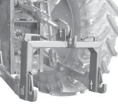
1.Back tractor into position and align draft links (A, Fig. 6) with draft link brackets on sickle bar.
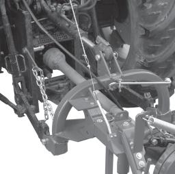
CAUTION: Before you work around hitch:
•STOP engine.
•LOCK park brake.
•FIRMLY block mower on horizontal surface.
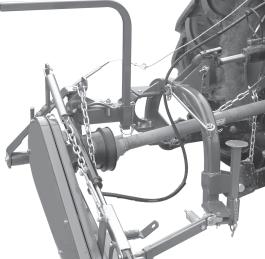
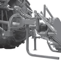
2.Connect the upper third-point and correctly regulate by adjusting the top link (B, Fig. 7). Place plate (C, Fig. 7) at the left side of the hitch integral with the same pin. Lock in place with the snap-in split pins (D, Fig. 8).
3.Hook the oscillating arms of the tractor to pins (E and F, Fig. 7). Lock in place with the snap-in split pins (G Fig. 8)
4.Lock the lift links using the relative chains (H, Fig. 7) and couplings parallel to the tractor. This operation must be carried out to prevent the machine from moving in a horizontal direction.
5.Install PTO shaft to tractor (Fig. 9).
IMPORTANT: Sickle bar MUST BE level front to rear.
Make sure PTO shaft is locked on the tractor PTO prior to engagement (I). Check that the guard (L) is free to turn and fix it with the relative latch (L1).
6.Remove the guard over the cutters (16, Fig. 4) and remove the tirant (7, Fig.4).
7.Lift-up sickle bar.
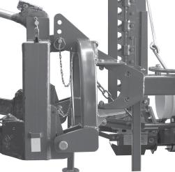
8.Remove spring locking pin (M, Fig. 10) from parking stand.
9.Remove support (N and O, Fig. 10) and remount them, upside-down in their seat .
10.Fasten with spring locking pin (M, Fig. 10).
PTO shaft adaption
The PTO shaft, supplied with the machine, is of standard length. Therefore it might be necessary to adapt the PTO shaft. Consult your dealer for the eventual adaptation.
Caution
• When the PTO shaft is fully extended, the two tubes must overlap by at least 6 inches (P Fig. 11). When fully inserted, the minimum play must be 1 37/64 inches (Q Fig.11).
• If the implement is used on another tractor, always check the above and that the guards copletely cover the rotating parts of the PTO shaft.
Attention
Comply with the manufacturer's instructions when transporting the mowing machine.
•The equipment installed can only be controlled by means of the PTO shaft complete with the necessary overload safety (i.e. clutch) devices and guards fastened with the appropriate chain.
•Only the PTO shaft supplied by the Manufacturer must be used.
•The engine must not be running when installing and removing the PTO shaft.
•Care must be taken regarding the safety and correct assembly of the PTO shaft.
•Use the chain provided to stop the PTO shaft from rotating.
•Always check carefully that the PTO shaft guard is always in position, both during transportation and operation.
•Frequently and set intervals check the PTO shaft guard, it must always be in excellent condition.
•Before engaging the PTO, check that the set rpm corresponds to that indicated by the sticker on the equipment.
•Before inserting the PTO, make sure that there are no people or animals nearby and that the rpm selected corresponds to that permitted. Never exceed the maximum admissible speed.
•Watch out for the rotating universal joint.
•Do not insert the PTO with the engine off or synchronized with the wheels.
•Always disconnect the PTO when the cardan shaft is at too wide an angle (never more than 10°,Fig. 12) and when it is not being used.
•Only clean and grease the PTO shaft when the power take-off is disconnected, the engine is off, the hand brake pulled and the key removed.
•When not in use, place the PTO shaft on the support provided for it.
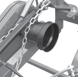
•After having dismantled the PTO, place the protective cover on the PTO shaft (R, Fig. 13).
Stability of sickle bar and tractor during transport
When a sickle bar is coupled to a tractor, so becoming an integral part of it for the purposes of road travel, the stability of the sickle bar-tractor complex may change and cause driving or operating difficulties (rearing up or side-slipping of the tractor). The condition of equilibrium can be restored by placing a sufficient number of ballasts on the front of the tractor so that the weights on the two tractor axles are distributed sufficiently evenly. To work in safety the instructions given in the highway code should be followed; these prescribe that at least 20% of the weight of the tractor alone should be borne by the front axle and that the weight on the arms of the hoist should not be more than 30% of the weight of the tractor itself. These factors are summarized in the following formulas:
Z > (M x s)-(0.2 x T x i) (d+i)
The amount of ballast that should be applied according to the formula is the minimum required for circulation on the road. If for reasons of tractor performance or to improve the set-up of the sickle bar during operation it is thought necessary to raise these values, please refer to the registration document of the tractor to check its limits. When the formula for calculating the ballast gives a negative result it will not be necessary to add any weight. In any case, as long as the limits of the tractor are respected, a suitable quantity of weights may be applied in order to ensure greater stability during travel. The symbols have the following meanings:
M Kg
Mass weighing on arms off hoist with full load (Te chnical data table)
T Kg Ma ss of tractor
Z Kg To tal mass of ballast i m Tra ctor wheelbase, that is, the horizontal distance between the tractor axles d m Ho rizo ntal distance between the centre of gravity of the ballast and the front axle of the tractor s m Ho rizo ntal distance between the centre of gravity of the operating machine and the back axle of the tractor
(please see Fig. 14 for reference):
Quick Coupler (optional)
1)Install hitch Quick Coupler (S, Fig. 15) on the tractor (see tractor operator manual).
2)Parking the sickle bar on a flat and compact ground supported by the relative supports. Then slowly move the tractor back until the Quick Coupler (S) is in range with the point hitches (T and U, Fig. 15).
3)Raise the Quick Coupler (S, Fig. 15) and make sure that sickle bar hitch is in the right position (Z, Fig. 16).
CAUTION: Before you work around hitch:
•STOP engine.
•LOCK park brake.
•FIRMLY block mower on horizontal surface.
Park vehicle safely
•Stop vehicle on a level surface, not on a slope.
•Disengage PTO.
•Engage the park brake.
•STOP the engine.
•Remove the key.
•Before you leave the operator’s seat, wait for engine and all moving parts to STOP.
Stay clear of rotating drivelines
Entanglement in rotating driveline can cause serious injury or death:
•Wear close fitting clothing.
•STOP the engine and be sure PTO driveline is stopped before getting near it.
Removing sickle bar
Removing
The sickle bar must be set-up on flat and compact ground, supported by the relative supports (A and B, Fig. 17).
1.Raise sickle bar.
2.Put parking stand (A and B, Fig. 17) in the DOWN position: install spring locking pin in order to secure parking stand (C, Fig. 17).
3.Lower sickle bar to the ground.
CAUTION: Before you work around hitch:
•STOP engine.
•LOCK park brake.
•FIRMLY block mower on horizontal surface.
4.Unhook the PTO schaft (, Fig. 18) from the tractor and put in on the special hook.
5.Remove quik-lock pin (D, Fig. 19) and pin (E, Fig. 19) from center link (F, Fig. 19).
NOTE: Put quik-lock pins and pins back into brackets on sickle bar for storage.
6.Remove draft links (J, Fig. 19) from draft link brackets (G, Fig. 19) by removing quiklock pins (H, Fig. 19) and pins (I, Fig. 19).
NOTE: Put quik-lock pins and pins back into brackets on sickle bar for storage.
7.Drive tractor forward slowly.
Removing sickle bar with Quick Coupler
1.Raise sickle bar.
2.Put parking stand (A and B, Fig. 17) in the DOWN position: install spring locking pin in order to secure parking stand (C , Fig. 17).
3.Lower sickle bar to the ground.
4.Raise the two Quick Coupler levers (V, Fig. 15) to unloch sickle bar (Quick Coupler Figure, page 14).
5.Lower Quick Coupler till further free the sickle bar.
Operate safely
Carefully read all the instructions before using the machine; if in doubt, contact the technicians of the Manufacturer’s dealer. The manufacturer declines all responsibility for the non-observance of the safety and accident prevention regulations described below.
General norms
1)Pay close attention to the danger signs in this manual and on the sickle bar.
2)The labels with the instructions attached to the machine give abbreviated advice for avoiding accidents.
3)Carefully observe, with the help of the instructions, the safety and accident prevention regulations.
4)Avoid touching moving parts in any way whatsoever.
5)Any work on and adjustment to the machine must always be done with the engine switched off and the tractor blocked.
6)People or animals must not, under any circumstances, be transported on the equipment.
7)It is strictly prohibited to drive the tractor, or allow it to be driven with the equipment attached by persons not in possession of a driver’s license, an expert or in poor conditions of health.
8)Before starting the tractor and the equipment, check that all safety devices for transport and operation are in perfect working order.
9)Before starting up the equipment, check the area surrounding the machine to ensure that there are no people, especially children or pets, nearby, and ensure that you have excellent visibility.
10)Use suitable clothing. Avoid loose clothing or garments with parts that could in any way get caught in the rotating or moving parts of the machine.
11)Before starting work, familiarize yourself with the control devices and their functions.
12)Only start working with the equipment if all the protective devices are in perfect condition, installed and in the safe position.
13)It is absolutely prohibited to stand within the machine’s radius of action where there are moving parts.
14)It is absolutely forbidden to use the equipment without the guards.
15)Before leaving the tractor, lower the implement coupled to the lift unit, stop the engine, engage the hand brake, remove the ignition key from the control panel, cover the cutters and outer skid with the relative guards. Raise the mowing bar (transport protection) according with the instructions given in this handbook.
16)The driver’s seat must never be left when the tractor engine is running.
17)Before operating the mowing machine, check that the support struts (A and B, Fig. 17 page 15) have been removed from underneath the implement. Make sure that the sickle bar has been correctly mounted and adjusted. Check that the machine is in perfect order and that all components subject to wear and deterioration are efficient.
18)Before releasing the equipment from the third point attachment, put the hoist command lever into the locked position and lower the support feet.
19)Only operate during daylight or with proper artificial light.
20)All operations must be carried out by expert personnel, equipped with protective gloves, in a clean and dust-free environment.
21)Do not climb onto the machine while it is running, even if it is stationary.
22)Before approaching the mowing bar, disengage the pto, switch off the tractor, engage the parking brake and check that the cutters are at a complete standstill.
23)The coupled implement may only be controlled through the PTO shaft complete with the necessary safety devices for overloads and with the guards fixed with the relative latch.
24)During maintenance and work operations, make sure that no other person goes near the tractor and the implement and accidentally works the controls with the risk of causing injury to persons and damage to property.
25)As a precaution, always set adeguate supports under the implement during assembly, servicing, cleaning or assembly work with the mowing bar raised.