
6 minute read
OPERATING

from Frontier Sickle Bar SB 3106 SB 3107 SB 31078 Operator’s Parts Catalog Manual(GH19502990) - PDF DOWNL

26)DO NOT wear radio or music headphones while operating the machine. Safe operation requires your full attention.
27)DO NOT operate the tractor and sickle bar when you are tired or ill.
Tractor hitch
1)Hook the equipment to a suitable, sufficiently-powered tractor by means of the appropriate device (lifter), in conformity with applicable standards.
2)The class of the equipment attachment pins must be the same as that of the lifter attachment.
3)Take care when working within the range of the lifting arms as this is a very dangerous area.
4)Be very careful when hooking and unhooking the equipment.
5) It is absolutely forbidden to stand between the tractor and linkage for acting the lifting controls from the outside (Fig. 20).
6)It is absolutely forbidden to stand in the space between the tractor and the equipment (Fig. 20) with the engine running.
7)The attaching of additional equipment onto the tractor brings about a different distribution of weight on the axles. Check the compatibility of the tractor performance with the weight that the mower transfers onto the three-point linkage. If in doubt consult the tractor Manufacturer.
8)Comply with the maximum admissible weight for the axle, the total mobile weight, transport regulations and the highway code.
Wear appropriate clothing
•Wear close fitting clothing and safely equipment appropriate for the job.
•Loud noise can cause impairment or loss of hearing, wear a suitable protective device such as earplugs.
Stay clear of rotating drivelines
Entanglement in rotating driveline can cause serious injury or death:
•Wear close fitting clothing
•Stop the engine and be sure PTO shaft is stopped before getting near it.
CAUTION: Before you work around hitch:
•STOP engine.
•LOCK park brake.
•FIRMLY block mower on horizontal surface.
Adapting the sickle bar
To ensure optium use, the sickle bar must completely project from the tractor (Fig. 21); three situations are shown in the Figure 22:
1)hitching to a tractor normally used for mowing jobs;
2)hitching to a large tractor;
3)hitching to a small tractor or to certain types of tracked vehicle.
When the frame joint is moved (A, Fig. 23), the position of the stop bushing (C, Fig. 23) of the cylinder linkage must consequently be changed, according to the cases shown in figures 23 and 24.
Adjustment
Before starting a mowing session, adjust the machine so that the best working setup is obtained. Correct machine setup guarantees excellent mowing, allows for the best machine-tractor performance and remarkably reduces wear of the cutting blades.
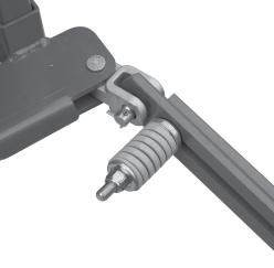
•Remove safety hook (D, Fig. 25), required only for transportation, and fit it back in the slot positioned above the chassis.
•Fit the sickle bar by adjusting the tractor tie-rods so that, when the sickle bar attachment is fitted to the three points on the tractor, the external tip of the cutting arm is approximately 2 inches. foward with respect to the arm base (Fig. 26).
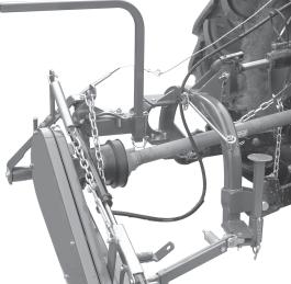
•Connect one end of the chain (F, Fig. 27) to the mower using the supplied pin and the other end to a stationary point on the tractor. Adjust the height of the mower to the ground (19.6 to 21.7 inches, Fig. 27) by moving the rings of the chain (F, Fig. 27) in the hole on the plate (G, Fig. 27). When the lifter is lowered, this precaution will constantly hold the mower at the same height from ground level. Also, check that the inner skid is still touching the ground and adjust the spring (K, Fig. 27) if necessary.
•Adjust inclination of the cutting arm teeth using tie rod (H, Fig. 28).
•Adjust the cutting height (Fig. 29) by moving the mowing bar on the holes of the inner mowing bar support (I), and, turning the nut of the outer mowing bar support (J), bring it level with the ground.
Mowing
•Remove the supports (L and M, Fig. 30) and remount them, upside-down in their seat . Install spring locking pin in order to secure parking stand (N).
•Remove tie rod from the cutting arm.
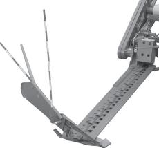
•The sickle bar is fitted with a safety device for protection against obstacles. If this device is tripped by impact with an obstacle, stop the tractor without raising the cutting arm. Check that the cardan shaft has not become seperated, if so, reassemble it. Position the safety tie rod parallel to the ground, and reverse the tractor until the safety tie rod hooks up again. If the tie rod releases easly, adjust spring (O, Fig. 31) using nut (P, Fig. 31 which should be tightened half turn at a time.
For successful mowing and to avoid jamming, we advise you to:
• Set and maintain the power take-off at a constant rate of 540 rpm to ensure correct blade frequency;
•Compatibly with the soil conditions and the type of grass, maintain a steady work speed: no slower than 5 mph to favor the discharging of the mown grass and no faster than 6.2 mph to avoid breaking or damaging the machine's structure.
•If the grass is tangled or flattened, keep the cutting bar grazing the ground.
Hazard bar
The hazard bar has been included with the equipment of the machine for safety reasons, to indicate the space occupied by the mower at work. For working, position the hazard bar in position (Q1, Fig. 32) and lock it in place with the screw (R). For transport put it in position (Q2).
Attention
If the blades becomes jammed, it is advisable to operate carefully wearing suitable personal protection. All the maintenance, adjustments and work preparation operations, must be carried out with the tractor strictly switched off and properly stationary, with the ignition key turned off and the sickle bar on the ground.
Caution
•Always raise the implement in order to reverse or change direction.
•The cutting arm should not be raised abruptly in order to avoid damaging the cutting blades.
•Power take-off must not exceed 540 r.p.m.
•Never run the engine at maximum power while mowing.
•In order to prevent breakages or damage, the speed of the tractor must never exceed 6.2 mph when the implement is working.
Danger
The mowing machine has sharp cutting blades. Always make sure that there are no persons, domestic animals, electrical cables, pipes and so forth, within the field of action of the implement.
Using the lifting device
Once you have positioned the equipment, prepare it for mowing:
•release the blade tie rod;
•remove the supports prop;
•remove the blade protection.
Operation of lifting device
Put the rope (S, Fig. 33) for releasing the bracket (T, Fig. 33) inside the tractor cabin.
Climb into the tractor and operate the hydraulic distributor to lower the blade (Fig. 34) into the mowing position.
CAUTION: While working regularly check that the bracket (T) is still resting along the cylinder rod (Fig. 35).
Raising of the cutter bar for road transport
•Fit the guards over the cutters and outer skid (C Fig. 47.
•From the tractor, pull the rope (S, Fig. 36) to disable the bracket (T, Fig. 36) and operate the hydraulic distributor to fully raise the cutter bar.
•Sicure it with the hooking tie rod.
Mowing on flat ground (or ground with small depressions)
For mowing operations on level ground, couple the lever mechanisms (V and Z, Fig. 37) in position (X, Fig. 37).
Lastly insert the lifting device as described in the previous paragraph.
With the rapid lifting device engaged, the bar (U, Fig. 38) has a negative inclination of -15° with respect to the horizontal plane during mowing, and a positive inclination that varies according to the lie of the land. This system has been devised for mowing quickly and safely on flat ground or ground with small depressions.
The operation of the lifting device up to the stop of the bracket on the cylinder (T, Fig. 39) allows the equipment to be raised by approx. 12.5 inches from the ground and, at the same time, an inclination of the blade (U, Fig. 39) of + 25°, so that the end of field maneuvers can be carried out.
Mowing on sloping ground
Figure 40 show type of mowing on sloping ground (banks, canals, etc.).
CAUTION: For mowing on surfaces that are not parallel to the tractor plane, we recommend removing the moving guide from the outer mowing bar support. To mount pulling of Figure 41 in order to improve the excursion and use of the sickle bar.
Only for mowing on sloping ground, it is necessary to prepare the machine according to the instructions given below:
1)Move the lever mechanisms (V and Z, Fig. 42) to position (Y).
2)Lift the bracket (T) as shown in Figure 42, and lock it with the rod (W) in the lower position of the slot (ref. W1, Fig. 42).
3)To avoid unpleasant problems during movement of the cutter bar, detach the steel cable (S) from the rod (W) and retrieve it up to position (S1) .
In this way the bar can be adjusted with the hydraulic cylinder to mow at different angles: from -45° to +90° with respect to the horizontal plane formed by the tractor (Fig. 43).
IMPORTANT:
The sickle bar can operates in each position between -45° to +90°.