2 minute read
OPTIONAL EQUIPMENT


Single Tailwheel Kit 5wp1001533
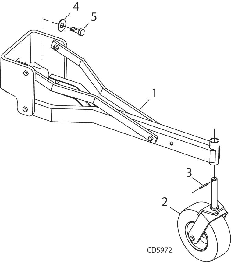
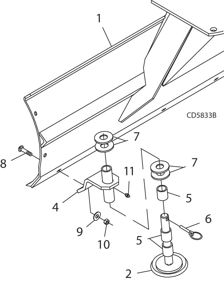
Assemble Tailwheel (Figure 10)
Notice
Floating links must be used with tailwheel to avoid equipment damage.
Tailwheel kit will not function properly when used with Quick Hitch.
Remove round retainer plate and hardware from rear of tilt turntable of rear blade (refer to Figure 5).
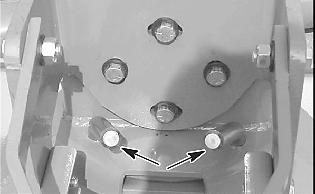
NOTE: Point drop pins in tilt turntable towards center of unit (Figure 11) before attaching tailwheel tube assembly.
Attach tailwheel tube assembly (1) to rear of tilt turntable and secure with cap screws (5) and hardened flat washers (4) from turntable. Torque cap screws to 170 lbs-ft. (231 N-m).
Attach yoke assembly (2) to tailwheel tube and secure into position with spirol pin (3).
Assemble Floating Link (Figure 12)
Attach right and left floating link brackets (14, 15) with offset to the inside on each side of the A-frame. Place sleeve (16) in forward hole and secure assembly into position using two cap screws (18) and lock nuts (19) as shown in Figure 12.
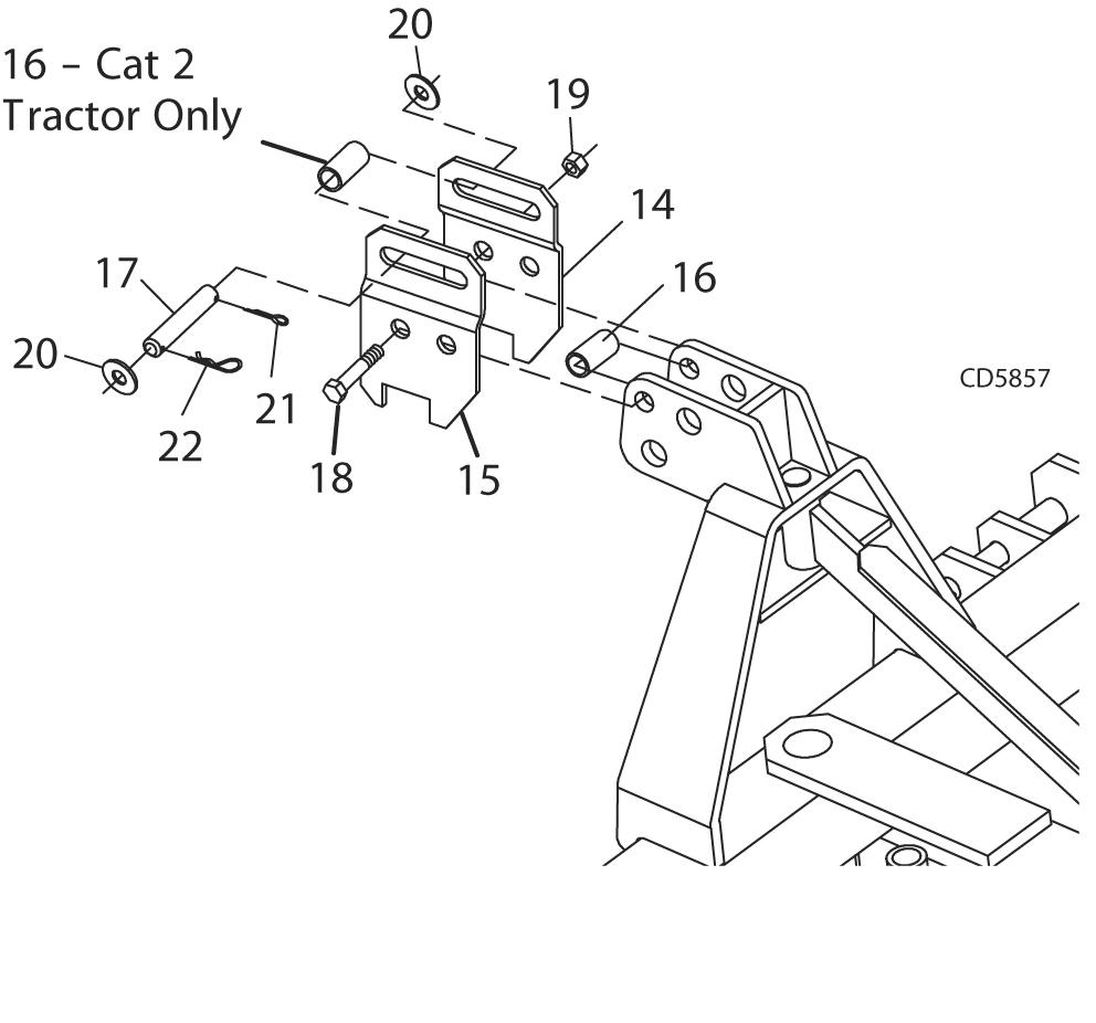
NOTE: When attaching to tractor, install clevis pin (17) into floating links using two 3/4" washers (20), one cotter pin (21), and hair pin (22) as shown.
1.Tailwheel tube assembly
2.Notat yoke assembly
3.3/8" Spirol pin
4.5/8" Hardened flat washer (from turntable)
5.5/8 NF x 1-1/2" Cap screw (from turntable)
14.Right floating link
15.Left floating link
16.Sleeve .78 x 1.00 x 2.00"
17.Clevis pin .75 x 4.38"
18.3/4 NC x 4-1/2" Cap screw GR5
19.3/4" NC Lock nut
20.3/4" Flat washer
21.3/16 x 1-1/2" Cotter pin
22.5/32" Hair pin cotter
Adjust Tailwheel Assembly
Set blade cutting edge 1/2" (13 mm) above the ground with the tractor 3-point hitch. Adjust tail wheel until tire is on the ground and the top link pin is centered in the floating link slot. Fine tune the grading height by raising or lowering the 3-point hitch.
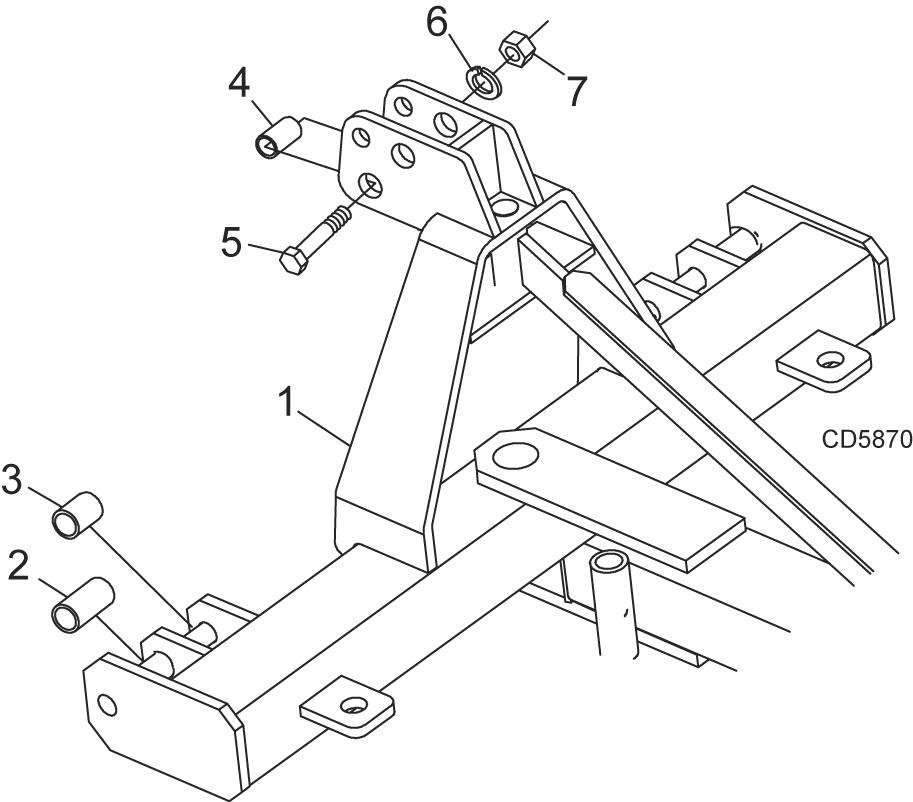
Quick Hitch Bushing Kit 5wp1002011
Notice
Do not use Quick Hitch with Single Tailwheel Kit.
Install cap screw (5), sleeve (4), lock washer (6), and hex nut (7) through bottom hole of A-frame as shown.
Install sleeves (2) for Category 2 tractors in outer pin locations. Install sleeves (3) for Category 1 tractors in inner pin locations as shown.
1.Moldboard assembly
2.Skid & shaft assembly
3.Right skid shoe bracket (not shown)
4.Left skid shoe bracket
1.A-Frame assembly
2.Sleeve, .94 x 1.44 x 2.75 Cat 2
3.Sleeve, .94 x 1.44 x 2.19 Cat 1
4.Sleeve, 1.0 x 1.25 x 2.06
5.1.0 NC x 5.0 Cap screw GR5
6.1.0 Lock washer
7.1.0 NC Hex nut
SKID SHOE KIT 5WP18300 (Figure 14)
Remove plow bolts from each end of cutting edge.
Attach right and left skid shoe brackets (3 & 4) to rear of moldboard with plow bolts (8), washers (9), and lock nuts (10) supplied in kit. Top of skid shoe brackets should angle slightly toward outer edge of blade.
Adjust skid shoe to desired height using washers (7) and spacers (5). One washer must be installed between the shoe bracket and the spacers.
Make sure skid shoe rotates freely to prevent premature skid pad wear.
5.Spacer, 1-1/4 sch 80 x 3/4" pipe
6.Pin, Klik 7/16 x 2"
7.1-1/4" Standard flat washer
8.Plow bolt, 5/8 NC x 2-1/2"
9.5/8" Standard flat washer
10.5/8" NC Hex lock nut
11.Grease fitting
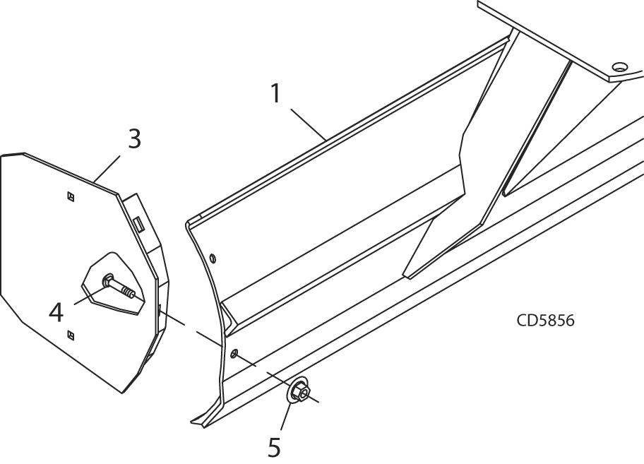
END PLATE KIT 5WP1001531 (Figure 15)
Install one end plate to each end of rear blade using two carriage bolts (4) and flanged lock nuts (5) on each end plate.
1.Moldboard assembly
2.End plate (right, not shown)
3.End plate (left)
4.1/2 NC x 1-1/4" Carriage bolt
5.1/2 NC Flanged lock nut