4 minute read
OPERATION


The operator is responsible for the safe operation of this equipment. Operators must be instructed in and be capable of the safe operation of the equipment, its attachments and all controls. Do not allow anyone to operate this equipment without proper instructions.
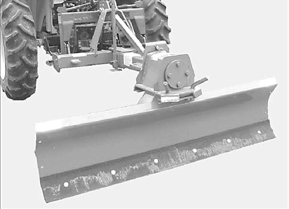
The Rear Blade is designed for a wide range of applications. The Rear Blade may be used for scraping, leveling, grading and backfilling and may be angled to windrow debris to the side for removal.
Optional kits are also available and included in this manual. The Single Tailwheel Kit is useful for grading and leveling work. The Skid Shoe Kit helps control cutting height when operating on hardened surfaces.
PRE-OPERATION CHECK LIST (OWNER’S RESPONSIBILITY)
___Check that all hardware is properly installed and secured.
___Do not allow riders.
___Review and follow all safety rules and safety decal instructions on page5 through page8.
___Check that equipment is properly and securely attached to tractor.
___Make sure tractor ROPS or ROPS CAB and seat belt are in good condition. Keep seat belt securely fastened during operation.
___Check that all safety decals are installed and in good condition. Replace if needed.
Caution
Always wear relatively tight and belted clothing to avoid getting caught in moving parts. Wear sturdy, rough-soled work shoes and protective equipment for eyes, hair, hands, hearing, and head; and respirator or filter mask where appropriate.
Connecting Rear Blade To Tractor
Rear blades are shipped completely assembled and may be installed on tractors equipped with a Category 1 or Category 2 3-point hitch.
The tractor draw bar must be removed or installed in its shortest position to allow the blade to rotate 180 degrees.
Never allow children or untrained persons to operate equipment.
Keep bystanders away from equipment.
Keep all persons away from operator control area while performing adjustments, service, or maintenance.
Never allow riders on power unit or attachment.
A minimum 20% of tractor and equipment weight must be on the tractor front wheels when attachments are in transport position. Without this weight, tractor could tip over, causing personal injury or death. The weight may be attained with a loader, front wheel weights, ballast in tires or front tractor weights. Weigh the tractor and equipment. Do not estimate.
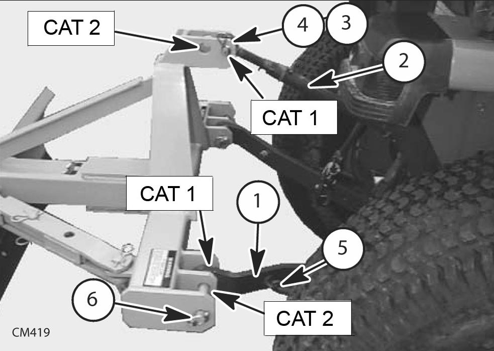
1.3-Point lower lift arm
2.Tractor top link
3.Retaining pin
4.Top link clevis pin
5.3-Point lower lift arm sway chain
6.Klik pin
Figure 1 . Connecting Rear Blade to Tractor
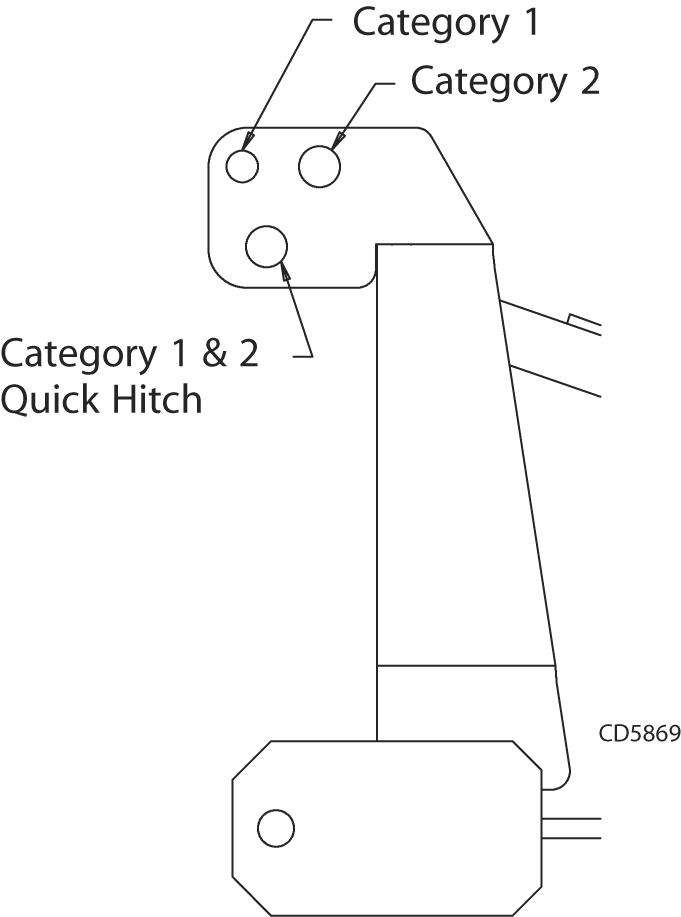
Refer to Figure 1. Place tractor 3-point lower lift arms (1) in the correct hitch position and install Klik pins (6) as shown (also refer to Figure 2). Category 1 tractor lift arms use inner hitch position. Category 2 tractor lift arms use outer hitch position with adapter sleeves installed over mounting pins. Secure lower link pins with lynch pins.
Attach tractor top link (2) to top hole of the A-frame and secure with the high strength clevis pin (4) and retaining pin (3) provided with top link. Category 1 top link attaches to front hole and Category 2 top link attaches to rear hole.
Adjust sway blocks or tighten tractor 3-point sway chains to eliminate implement side-to-side movement during operation.
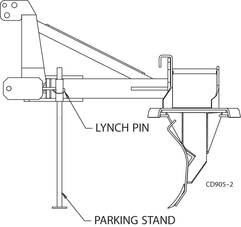
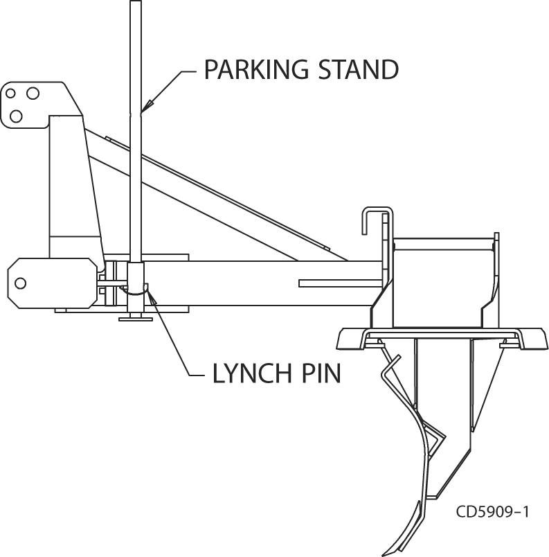
Storage Position
With rear blade raised, place parking stand in lowest position as shown in Figure 4. Lower rear blade so cutting edge and parking stand are flat on the ground. Disconnect 3-point arms and top link from rear blade.
Optional Quick Hitch Bushing Kit
An optional quick hitch bushing kit is available for Category 1 and Category 2 tractors. See page14 for installation instructions.
Notice
Do not use Quick Hitch with Single Tailwheel Kit.
Parking Stand Placement Operating Position
Place parking stand in the raised position during operation. This position allows the moldboard to rotate 360 degrees. Secure into position with 3/8 x 2-1/4 lynch pin as shown in Figure 3.
Adjustments
NEVER GO UNDERNEATH EQUIPMENT. Never place any part of the body underneath equipment or between moveable parts even when the engine has been turned off. Hydraulic system leak-down, hydraulic system failures, mechanical failures, or movement of control levers can cause equipment to drop or rotate unexpectedly and cause severe injury or death.
•Service work does not require going underneath.
•Read Operator's Manual for service instructions or have service performed by a qualified dealer.
Adjustments to the rear blade require raising the blade slightly off of the ground. Do not leave the tractor operator position with the blade raised except to make blade adjustments during operation.
To make blade adjustments, raise the blade just high enough to allow blade to pivot without dragging on the ground. Shut off the tractor engine, set the park brake, remove the key, and carefully leave the operator position.
Never place any part of your body underneath the blade or 3-point hitch while making adjustments. Hydraulic leak-down or failure can cause the blade to fall suddenly.
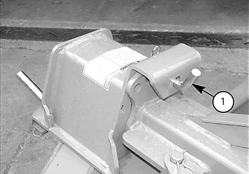
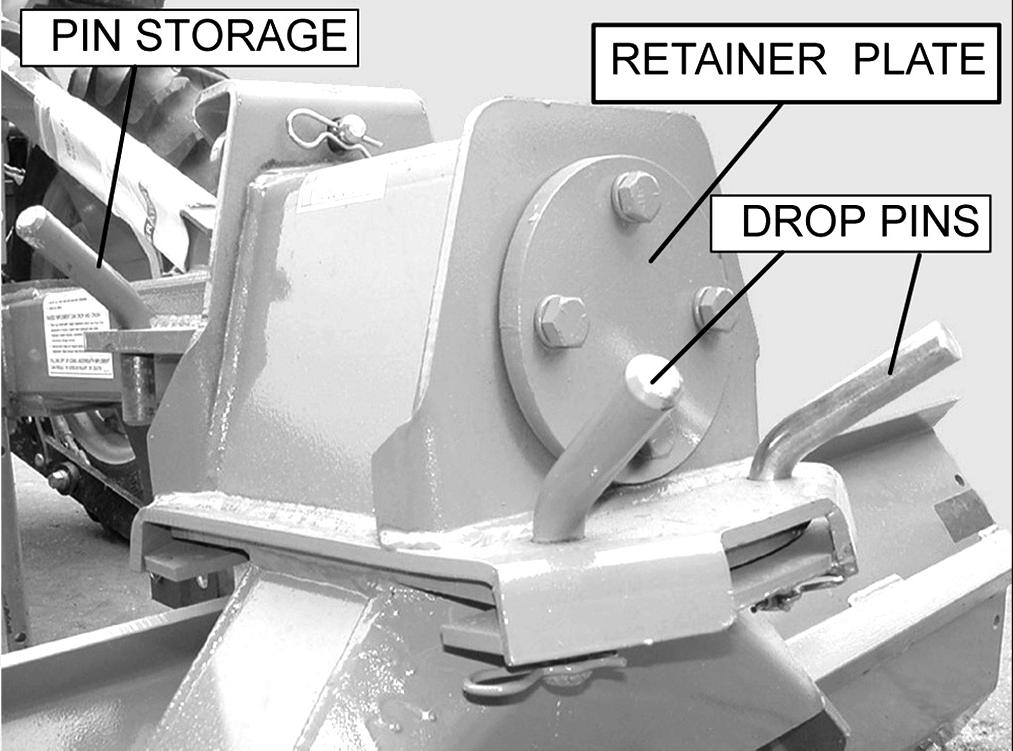
Angling and Reversing (Figure 5)
Ten holes are provided for angling the blade: five in the forward position (to a maximum angle of 45 degrees) and five in the reverse position. Lift the drop pins, swing the blade to the desired angle or to the reverse position, then reinsert the drop pins to lock the blade in place.
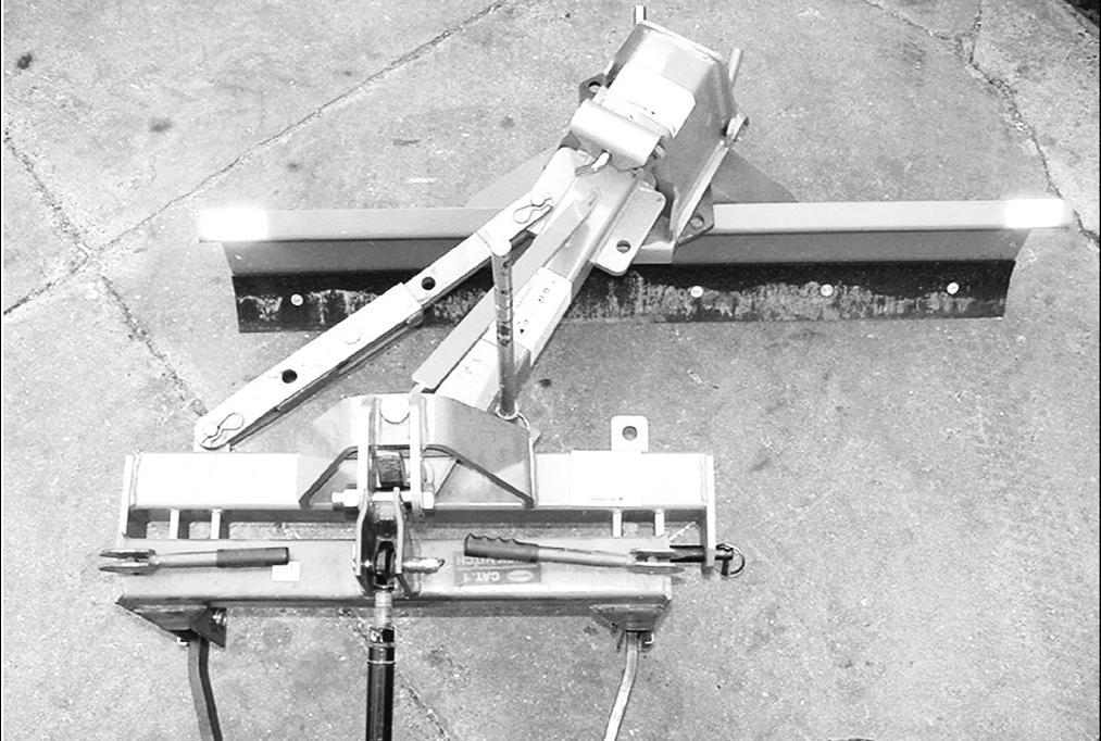
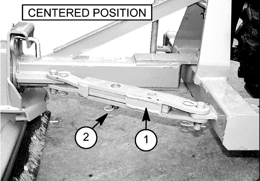
age in place by inserting the pin in the desired hole. Secure with hair pin clip. For offsetting to the left, position the linkage on the right side of the frame and extend the linkage.
The frame will swing to the right or left. For offsetting the frame to the right, position the standard mechanical linkage (1) on the left side of the frame.
Blade Pitch
The pitch of the blade can be changed by adjusting the top link of the tractor.
Blade Tilt (Figure 8)
The blade will tilt so that one end of the moldboard is lower than the other. Remove yoke pin (1), tilt the blade to the desired angle, replace the pin, and secure with the hair pin clip. Additional tilt adjustment can be made with the tractor 3-point hitch leveling crank.
1.Mechanical
Extend the linkage by pulling the center pin (2) and swinging the frame to the desired angle. Lock the link-
Blade Rotation (Figure 9)
The blade can be reversed for backfilling. Remove the drop pins and rotate the blade 180 degrees from the forward position. Reinstall the drop pins and secure. The tractor draw bar must be removed or installed in its shortest position to allow the blade to rotate 180 degrees.
Adjust sway blocks or tighten tractor 3-point sway chains to eliminate implement side-to-side movement during operation.
Notes