5 minute read
DEALER SERVICE


DEALER SET-UP INSTRUCTIONS
Assembly of this equipment is the responsibility of the dealer. It should be delivered to the owner completely assembled, lubricated, and adjusted for normal operating conditions.
In most cases the Ground Seeder is shipped completely assembled from the factory. The Legume seed boxes, front disc roller, front studded roller and cultipacker are options that can be added to the Ground Seeder at a later time if desired.
Optional Accessories
Front Spike Roller (For illustration, see page40)
1. Place seeder on level surface with jack stands under 2 x 3 front frame tube.
2. Stop engine and set parking brake.
3. Place hoist strap around disc gang axle.
4. Remove 3/4” U-bolts and nuts connecting 2 x 3 tube to disc gang.
5. Using hoist strap, carefully remove disc gangs from underneath seeder.
6. If 48” seeder, remove 2 x 3 tube and replace with roller 2 x 3 tube. Install 5/8” bolt, nut, 5/8” bent pin and hair pin clip. If 60” seeder, use existing 2 x 3 tube.
7. Carefully position disc under frame and attach to 2 x 3 tube using 3/4” U-bolts and nuts. Allow mounts to locate naturally to 2 x 3 tube when tightening hardware without allowing them to twist or cock. Position disc gangs with 1-1/2” gap between middle axle shafts.
■ Notched disc blades are sharp. Wear gloves and tight fitting clothing.
Legume Seed Box (For illustration, see page38)
1. Place seeder on level surface.
2. Stop engine and set parking brake.
3. Open Cool Season seed box shield.
4. Remove SMV sign from Cool Season seed box saving 1/4” hardware.
5. Install Legume seed box on seeder frame and Cool Season box using 3/8” hardware and 5/16” hardware respectively.
6. Remove short agitator chain from Cool Season seed box.
■ Notched disc blades are sharp. Wear gloves and tight fitting clothing.
6. If 48” seeder, remove 2 x 3 tube and replace with disc 2 x 3 tube. Install 5/8” bolt, nut 5/8” bent pin and hair pin clip. If 60” seeder, use existing 2 x 3 tube.
7. Carefully position front rollers under frame and attach to 2 x 3 tube using 3/4” U-bolts and nuts. Allow mounts to locate naturally to 2 x 3 tube when tightening hardware without allowing them to twist or cock. Position rollers with 1/2” gap between middle end shafts.
Front Disc (For illustration, see page41)
1. Place seeder on level surface.
2. Stop engine and set parking brake.
3. Place hoist strap around front roller.
4. Remove 3/4” U-bolts and nuts connecting 2 x 3 tube to roller.
5. Using hoist strap, carefully remove rollers from underneath seeder.
7. Install Legume drive chain around Cool Season seed cup sprocket, around Cool Season seed box agitator sprocket, underneath Legume idler sprocket and around Legume seed cup sprocket.
8. Install SMV sign on Legume box with 1/4” hardware.
9. Install Legume shield to Cool Season box shield with 1/4” hardware.
10. Install seed cup PVC tubes on seed cups and insert into Legume transition tray.
Cultipacker (For illustration, see page42)
1. Place seeder on level surface.
2. Stop engine and set parking brake.
3. Match cultipacker mounts with holes in frame and install 3/4” x 1-1/2” bolt, 3/4” washers (48” GS10 only) and 3/4” flanged lock nuts. Place washer between frame and cultipacker mounts.
4. Install spring stops on frame.
5. Install spring rods and springs on cultipacker arm and in holes of spring stops.
6. Adjust jam nuts on spring rods to tighten spring to desired setting.
(Rev. 5/08/2020)
Hydraulic Tow Kit (for illustration, see page49 & page50)
1. Place seeder on level surface.
2. Remove 7/8” lower hitch pins from seeder hitch lugs. Remove 5/8” bolt and sleeve from limited Cat 1 top link location.
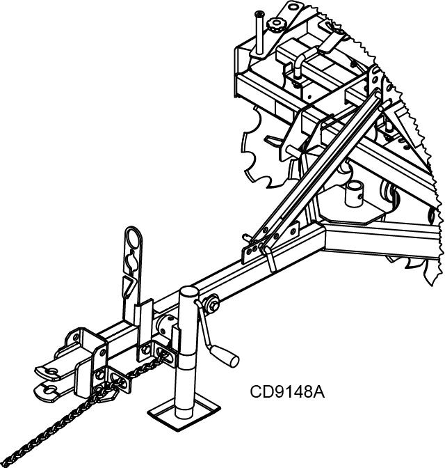
3. Align tow kit tongue between lower hitch lugs and attach using 7/8” lower hitch pins and retain with klik pins.
4. Mount jack stand to tongue using pin provided with the jack.
NOTICE: There are two locations for the jack stand. Mount to tongue tube for storage and on “Y” section during operations.
5. Install tongue adjustment channel between mast plates with 5/8” bent pin and retain with hair pin clip.
6. Install hitch to tongue with 5/8” x 6” bolt, safety chain eyelet bracket, and 5/8” lock nut. The 3/4” x 4-3/4” pin should be installed during operation; removal of pin can provide additional adjustment to attach to tractor.
7. Install hose holder over tube with 5/8” x 3-3/4” bolt, safety chain eyelet bracket, and lock nut approximately 5.5” from the hitch. DO NOT COVER DECALS.
8. Install safety chain rear chain link through both eyelet brackets. Insert 5/8 3 – 3/4” bolt through thick plated washer, safety chain rear chain link, hole in tongue and fasten with 5/8” lock nut.
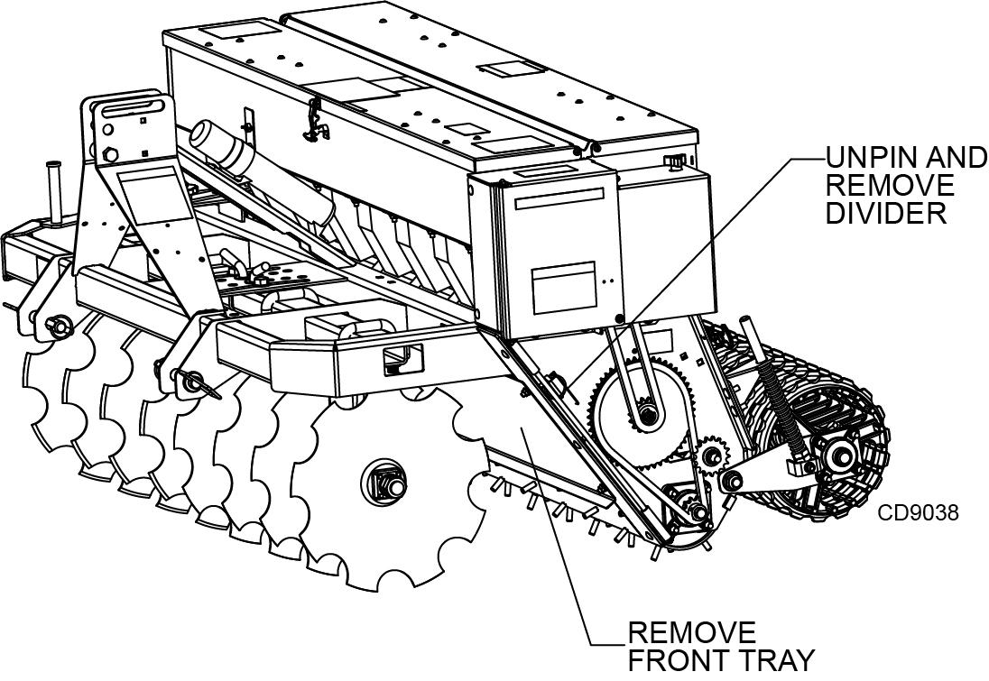
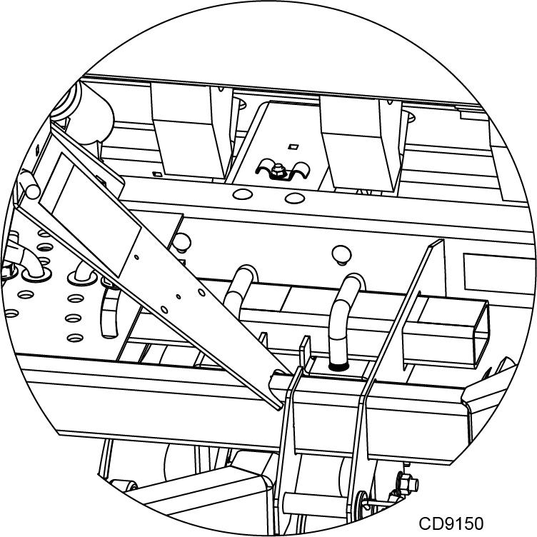
9. Remove Cool Season seed box divider and front tray. See Figure 32. Ensure front tool is in a forward position to avoid interference during installation. Refer to page13 for front tool adjustment.
10. Secure 5/16” x 1” carriage bolt on frame stiffener with push-on washer; this will be used to secure hydraulic hoses. Install frame stiffener using 3/8” x 1” carriage bolts and lock nuts.
11. Align hydraulic cylinder mount with slots on z-plate, at the rear of the seeder. Mount using 3/8” x 1-1/4” bolts and lock nuts.This mount connects the seeder frame and frame stiffener previously installed.
12. Open lower chain shield to install left mounting bracket. Left and right mounting brackets use four 3/8” x 1” carriage bolts and lock nuts.
NOTICE: If cultipacker option is installed, remove cultipacker stops. Mounting brackets contain cultipacker stops within design.
■ Loosen jam nuts on cultipacker spring rods until springs are unloaded before removing spring stops.
13. Align the pivot arm tubes with mounting brackets. Mount using 5/8” x 3-3/4” bolts and lock nuts. Do not over-tighten.
14. Connect hydraulic cylinder to cylinder mounting bracket and pivot arm using pin provided with cylinder and 1” x 4” pin, respectively. Cylinder lock aligns with mounting location on pivot arm. Secure in unlocked position with 5/8” bent pin and hair pin clip.
15. Mount wheel arms to pivot tube using 1/2” x 4” bolts and lock nuts.
NOTICE: Install wheel arms to an outside most position. Instability during transport can occur if wheel arm spacing is narrow.
16. Install tires to wheel arms with 3/4” washer, castle nut, and cotter pin. Install hub caps.
17. Install the SMV mount and sign to pivot arm tube ears with 1/4” x 1-3/4” bolts and nuts.
NOTICE: SMV sign should be mounted to the center most possible position or left of unit center.
18. Install two 3/8” NPT to 9/16” JIC adapter to cylinder ports. Install four 9/16” JIC to 3/4” ORB adapters to relief valve ports. Mount valve to left side mast plate using 5/16” x 2-1/2” bolts and nuts.
19. Route 54” hoses from cylinder to valve. Mount to frame stiffener with butterfly clamp and secure with 5/16” nut.
20. Route 94” hoses from valve to hitch. Install 1/2” NPT to 9/16” JIC adapters and quick couplers to tractor side.
21. Reinstall Cool Season seedbox divider, front tray, and close lower chain shield.