10 minute read
OPERATION


The operator is responsible for the safe operation of this seeder. The operator must be properly trained. Operators should be familiar with the equipment, the tractor, and all safety practices before starting operation. Read the safety rules and safety decals on page5 through page9.
Recommended tractor ground speed is from 2 to 5 mph. Power unit must be equipped with Roll Over Protection System (ROPS) or ROPS cab and seat belt. Keep seat belt securely fastened. Falling off power unit can result in death from being run over or crushed. Keep foldable ROPS system in “locked up” position at all times.
Never allow children or untrained persons to operate equipment.
Keep bystanders away from equipment. Keep hands, feet, hair, and clothing away from equipment while engine is running. Stay clear of all moving parts.
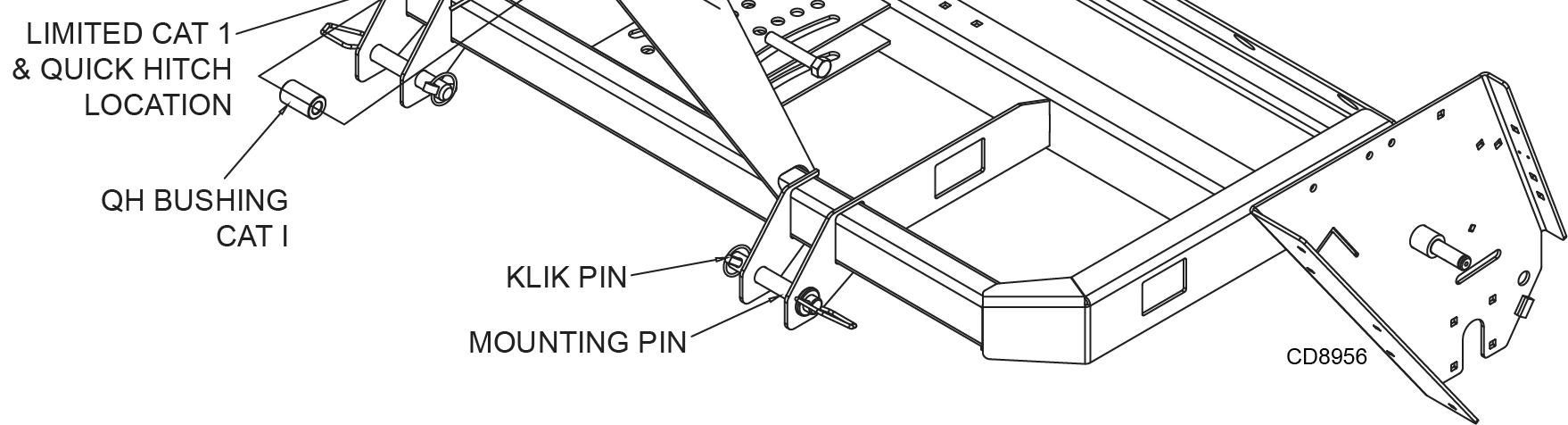
NOTICE: The Ground Seeder is designed for use on Category I, 3-point hitch tr actors. See page4 for specifications.
NOTICE: For Cat I fixed hitch usage, remove Quick Hitch 5/8" bolt, nut and sleeve to prevent damage to tractor’s 3-point top link.
1. Attach the tractor’s lower lift arms to the seeder and secure with mounting pins and klik pins. See Figure 2.
2. Attach the tractor’s top link to the mast plates of the seeder. The seeder can be operated in a float or fixed 3-point hitch position.
Stop power unit and equipment immediately upon striking an obstruction. Turn off engine, set parking brake, remove key, inspect, and repair any damage before resuming operation.
Always wear relatively tight and belted clothing to avoid getting caught in moving parts. Wear sturdy, rough-soled work shoes and protective equipment for eyes, hair, hands, hearing, and head; and respirator or filter mask where appropriate.
Attaching Ground Seeder To Tractor
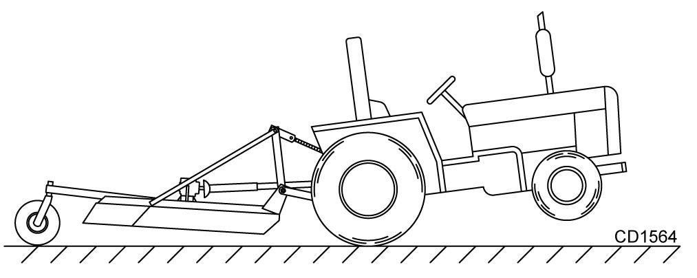
A minimum 20% of tractor and equipment weight must be on the tractor front wheels when attachments are in transport position. Without this weight, front tractor wheels could raise up resulting in loss of steering. The weight may be attained with front wheel weights, ballast in tires, front tractor weights or front loader. Weigh the tractor and equipment. Do not estimate.
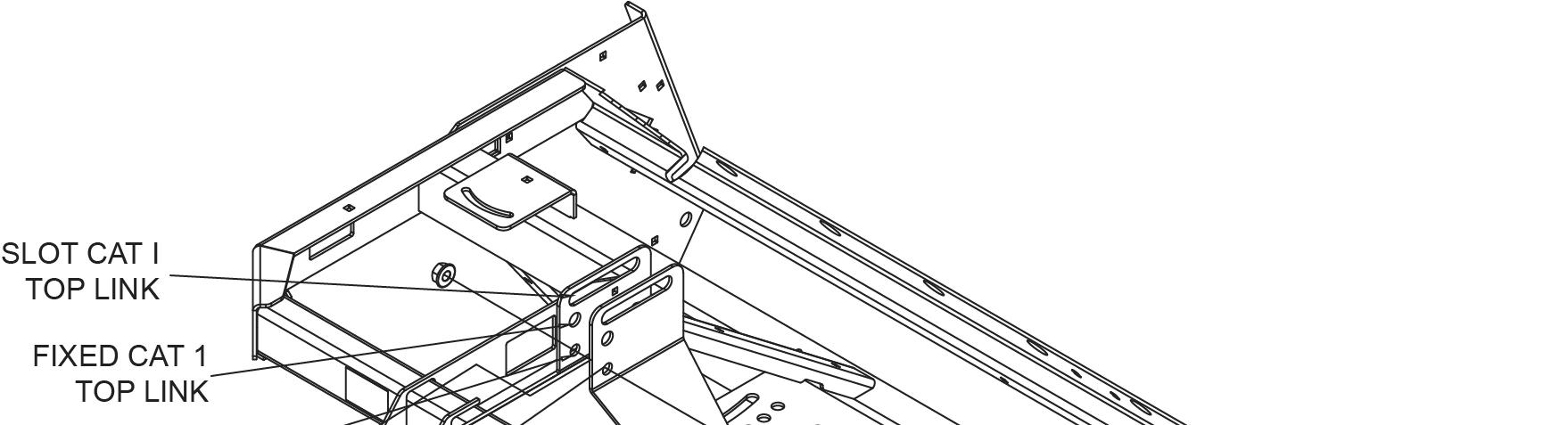
For beginning usage, the float position is recommended. See Figure 2. To enable the seeder to follow the contours of uneven ground, install the tractor’s top link in the long slot in the top of the mast plates. For proper float (up and down) the top link pin should be centered in the slot (recommended for beginners).
For controlled depth of tillage, use the fixed top link position in the mast plates. See Figure 2.
For quick hitch use, install the available quick hitch bushings. The seeder will not float with a quick hitch installed. An optional Quick Hitch Bushing Kit, P/N 5WD1022043 is available.
3. Adjust the lower lift arm anti-sway device to prevent excessive side-to-side movement of the seeder.
4. Weigh tractor and seeder with seeder in transport position. If necessary, add weight to obtain a minimum of 20% of tractor and implement weight on tractor front wheels. Weight may be attained using front wheel weights, ballast on tires, front roller weight, or front loader.
Hitching Ground Seeder With Tow Kit
■ Make sure shields and guards are properly installed and in good condition. Replace if damaged.
■ Never use an intermediate support as the primary attaching point for safety chain.
■ Never operate seeder equipped with tow kit without safety chain properly attached to tractor. Replace safety chain if any links or fittings are damaged or deformed.
1. Park seeder and tractor on a level, hard surface.
2. Adjust clevis hitch bracket on tow kit tongue so it is level when attached to the tractor.
3. Adjust the parking jack to match tow kit tongue height to the tractor drawbar height.
4. Pin the tongue to the tractor drawbar.
NOTICE: When attaching seeder to tractor drawbar, make sure the correct drawbar pin is used. A Category 1 drawbar pin is Ø1". Failure to use the correct pin size will result in premature wear of hitch and drawbar hole. If the hitch on the seeder doesn’t match your tractor drawbar, contact your dealer to order the correct size hitch for your tractor. If se eder will be attached to tractor for a long period of time, secure hitch to drawbar using a bolt, locknut, and washers assembled tightly. This will reduce wear on drawbar and hitch.
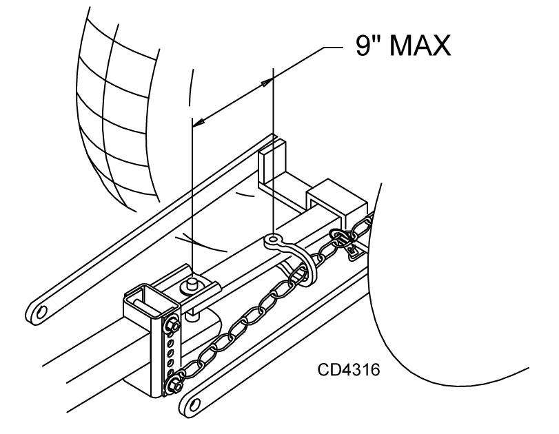
5. Attach the safety chain to the tractor with the maximum distance between hitch pin and
(Rev. 5/08/2020) intermediate support/primary attaching point. See Figure 3. Route safety chain through hose holder when not in use.
NOTICE: Attach safety chain to tractor with the minimum possible slack in the chain. Failure to reduce the slack could cause failure of hoses/wires and damage primary components of the implement and/or attached accessories.
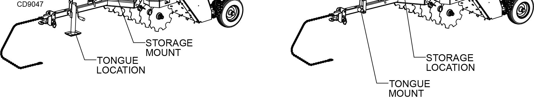
6. Lower the parking jack until the tongue weight is fully supported by the drawbar and the jack foot is off the ground. Unpin the jack from the tongue.
7. Pin the jack to the operation location on top of the "Y" section on tongue. See Figure 4. This location prevents accidental contact with the rear tractor tires, which could result in damage to the jack.
Attaching Electronic Harness
1. Attach wire harness from seeder to tractor.
2. Route wire through the guide on the tow kit tongue and be sure the wire can slide freely in the guide. Do not allow wire slack to drag on the ground or become caught on tractor protrusions.
Attaching Hydraulic Hoses
1. Attach hydraulic hoses from the seeder to the tractor.
2. Route the hoses through the hose guide on the tow kit tongue and be sure the hoses can slide freely in the guide. Do not allow hose slack to drag on the ground or become caught on tractor protrusions.
3. From the operator position, start the tractor, then raise and lower the seeder several times. This will purge the hydraulic cylinder and hoses of trapped air.
Interference Check
1. Be sure that the tractor 3-point arms do not interfere with wire harness / hydraulic hoses or tow kit components.
2. Check for straight ahead operation and full turning angles. If there is any interference, remove the 3point arms.
IMPORTANT : Contact between 3-point arms and seeder/tow kit can cause damage, especially when turning.
Ground Seeder Attitude Adjustment
The Ground Seeder can be used as both a tillage tool and a seeding tool. When used strictly as a tillage tool, a nose-down attitude will provide the most aggressive tillage. When used for tilla ge and seeding at the same time, a level attitude is preferable. If the Ground
Seeder is being used to se ed already-tilled soil, a slight nose-up attitude may be preferable for minimum soil disturbance. With the seeder connected to the tractor, attitude adjustments can be made by following these instructions:
Nose - Down Attitude Adjustment
3-Point Mounted
1. Lower seeder to the ground.
2. Pin the tractor top link into the fixed top link hole.
3. Shorten the tractor top link length until the drive roller has been lifted off the ground a distance equivalent to the desired tillage depth. Fix the top link length by tightening the jam nut on the top link.
4. Resume operation and check performance. Repeat as necessary.
Drawbar Mounted
1. Lower seeder to the ground.
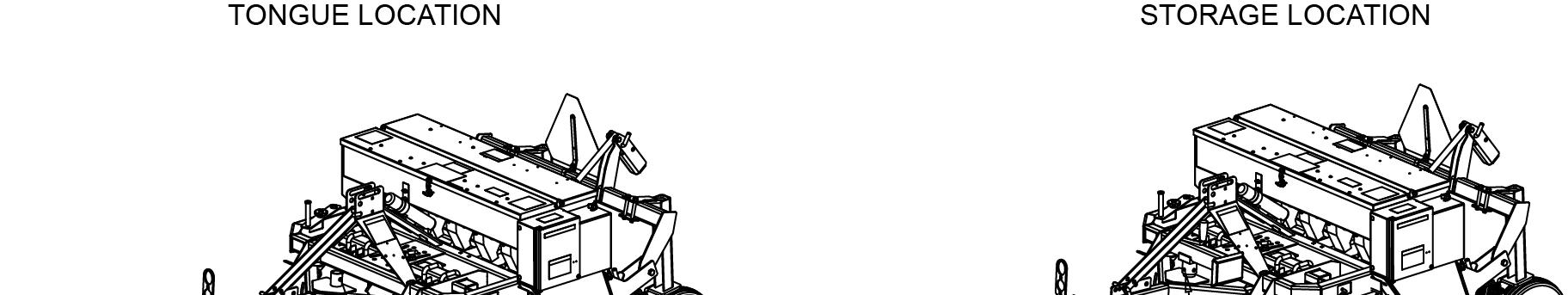
2. With jack stand in the storage location and seeder engaging the ground, unpin the adjustment channel from tongue. Pinning farther from seeder will provide more aggressive tillage.
3. Use jack stand to align adjustment channel with appropriate hole on tongue. Pin in desired location.
4. Resume operation and check performance. Repeat as necessary.
Nose - Up Attitude Adjustment
3-Point Mounted
1. Lower seeder to the ground.
2. Pin the tractor top link into the fixed top link hole.
3. Lengthen the tractor top link length until the front tool as been lifted off the ground a sufficient distance. Fix the top link length by tightening the jam nut on the top link.
4. Resume operation and check performance. Repeat as necessary.
Drawbar Mounted
1. Lower seeder to the ground.
2. With jack stand in the storage location and seeder engaging the ground, unpin adjustment channel from tongue. Pinning closer to seeder will provide less ground engagement.
3. Use jack stand to align adjustment channel with appropriate hole on tongue. Pin in desired location.
4. Resume operation and check performance. Repeat as necessary.
NOTICE: Excessive forward or rear attitude adjustment will lead to poor performance and may cause equipment damage or premature bearing failure.
Ground Seeder Tool Operation
The Ground Seeder is an excellent turf reconditioning tool, Cool Season seeder, food plot and conservation seeder. Its ground penetration promotes a healthy root system by allowing water, air, and sunlight to enter the roots.
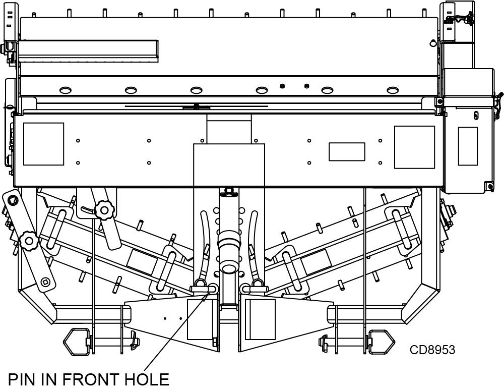
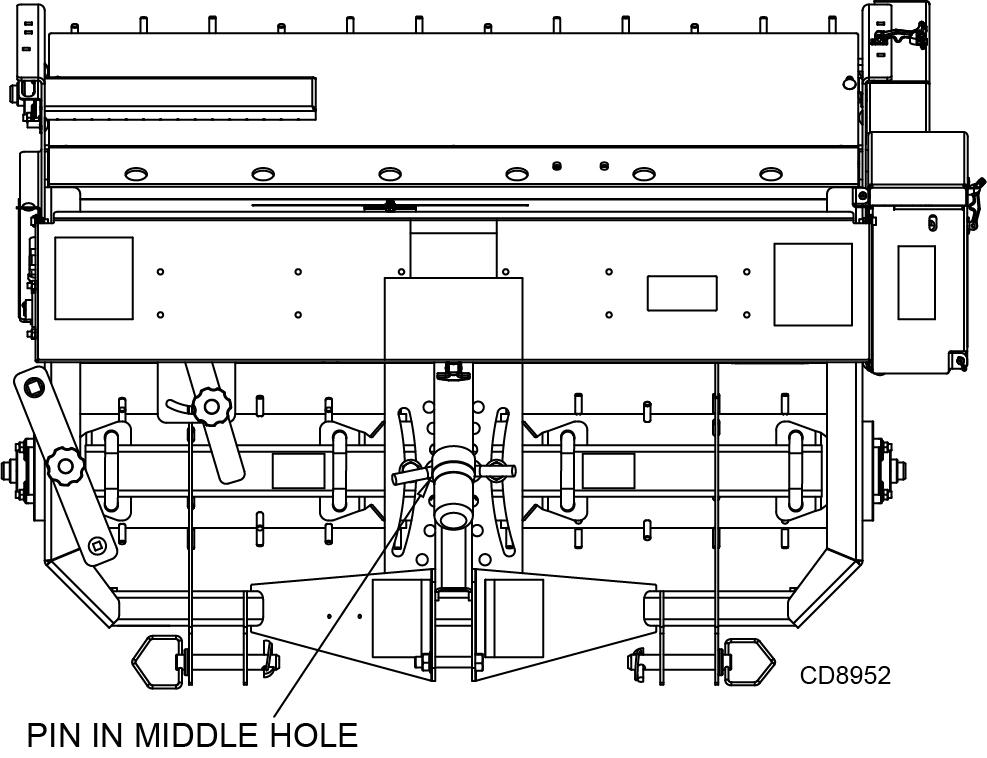
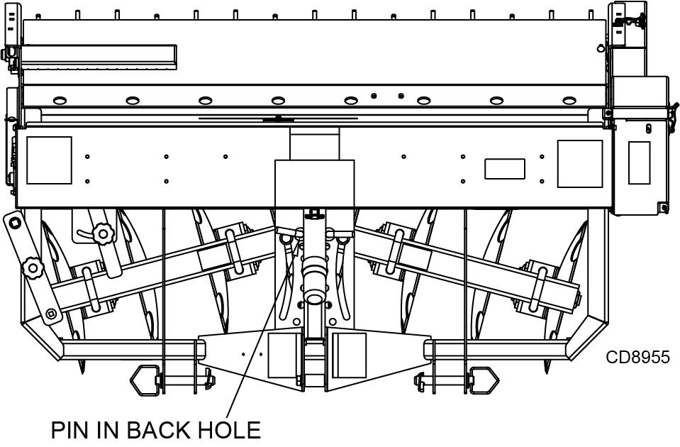
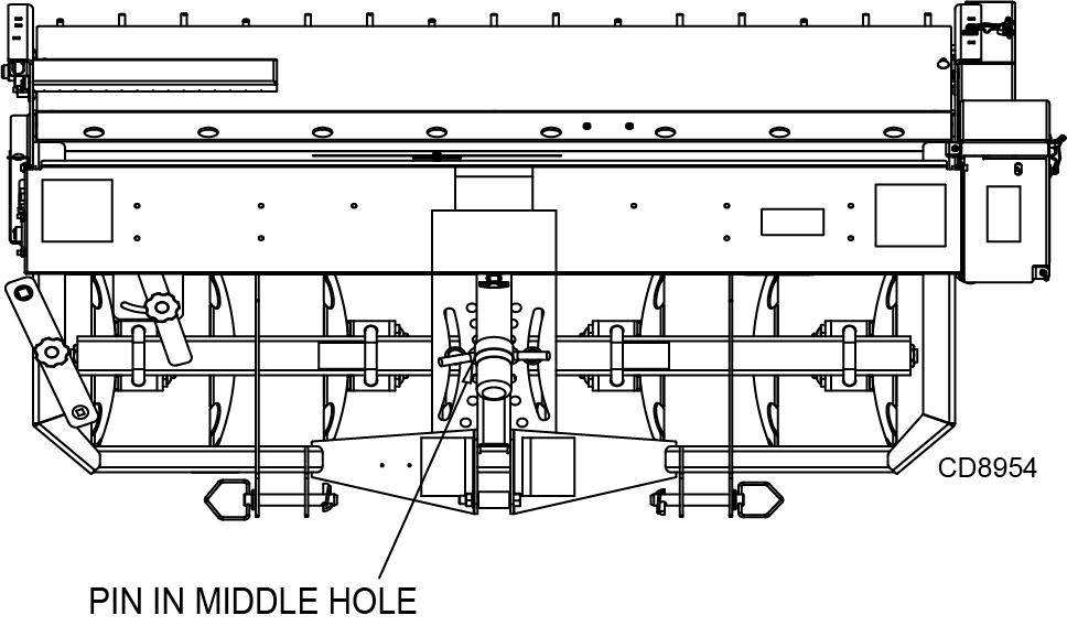
Front Rollers roller pins. For severe turf conditions, the maximum angle position may be desired (Figure 6).
When the front rollers are straight (Figure 5) and the seeder is pulled forward, the front roller pins will penetrate the soil in a straight pushing action, causing little disturbance to the turf.
The front rollers can be angled to promote a more aggressive tearing action of the turf. The greater the angle, the more tearing action is applied by the front
5WPMAN1285 (5/07/2019)
Adjusting Front Roller Angle
1. Position tractor and Overseeder on a level surface.
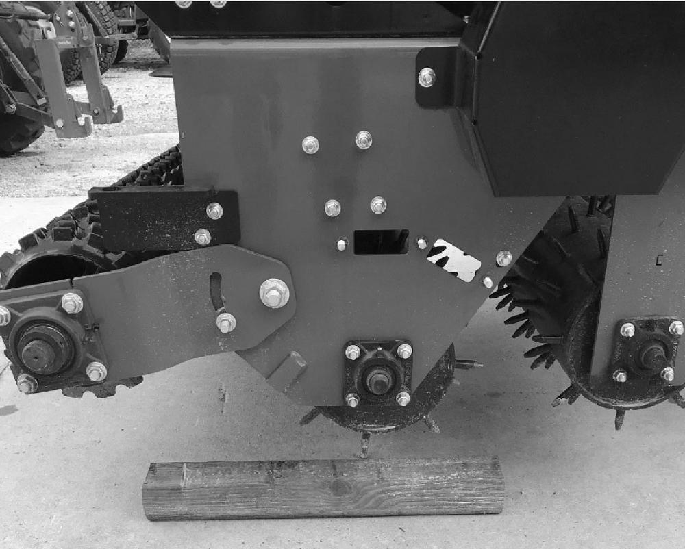
2. Place wooden blocks (minimum 4" thickness) on ground to align with each end of Overseeder drive roller. Raise seeder slightly off the ground and position the Overseeder over wooden blocks by moving tractor. Do not allow wooden block to contact the front roller. See Figure 7.
3. Lower Overseeder to resting position on wooden blocks for support during front roller adjustment. (Follow tractor safe parking procedure in tractor operator’s manual.)
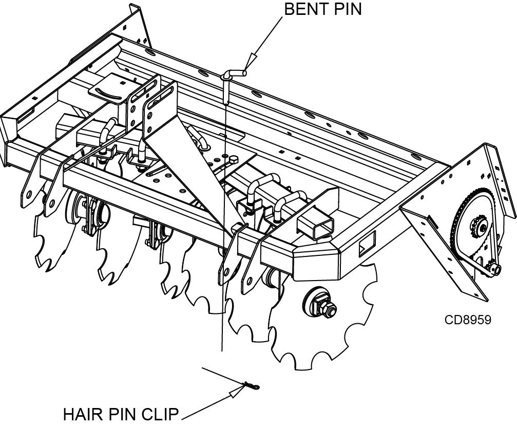
4. Remove bent pins and hair pin clips from seeder front tool adjustmen t. See Figure 8.
5. Adjust RH and LH front gang assemblies independently. Move tubes forward (see Figure 8) for spiked front rollers. Keep RH and LH adjustment angles the same for proper operation.
6. Reinstall bent pins to hold adjusted position.
7. Lift Overseeder and pull forward to clear wooden blocks. Lower Overseeder to rest position on the ground/level surface and install hair pin clips (see Figure 8).
8. Reverse this procedure to move front rollers back to straight position.
Front Disc
The front disc tool can be used to prepare a seedbed without the need for prior use of a separate disc or tillage tool. When the discs are straight (Figure 9), the seeder has little soil disturbance. When the discs are angled fully backward (Figure 10), there is maximum soil disturbance and the seedbed can often be prepared in two or three passes. The disc has three angled positions to provide an array of soil penetration depths and seedbed preparation.
Adjusting Front Disc Angle
1. Position tractor and Overseeder on a level surface.
2. Place wooden blocks (minimum 4" thickness) on ground to align with each end of Overseeder drive roller. Raise seeder slightly off the ground and move tractor to position the Overseeder over wooden blocks. Do not allow wooden block to contact the front disc (Figure 7).
3. Lower Overseeder to resting position on wooden blocks for support during front disc adjustment. (Follow tractor safe parking procedure in tractor operator’s manual.)
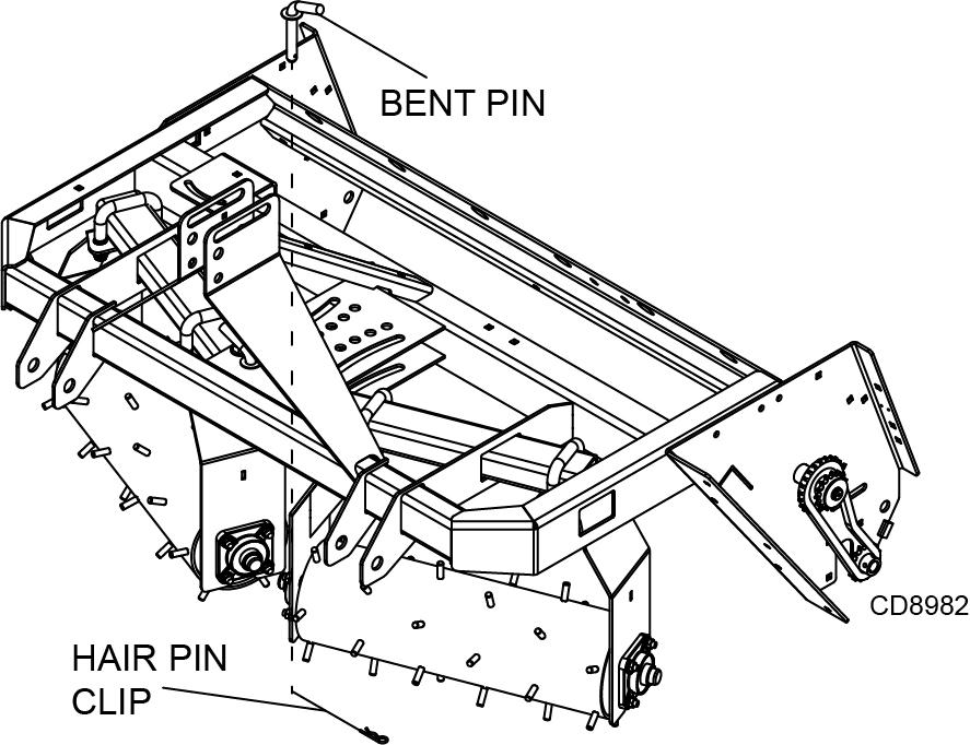
4. Remove bent pins and hair pin clips from seeder front tool adjustment (Figure 11).
5. Adjust RH and LH front gang assemblies independently. Move tubes rearward (Figure 11) for concave disc blades. Keep RH and LH adjustment angles the same for proper operation.
6. Reinstall bent pins to hold adjusted position.
7. Lift Overseeder and pull forward to clear wooden blocks. Lower Overseeder to rest position on the ground/level surface, and install hair pin clips (Figure 11).
8. Reverse this procedure to move front discs back into straight position.
Important
■ Do not operate seeder in reverse. Operating seeder in reverse may result in damage to seed boxes and chain drive system.
Rear Roller
The rear roller firms and presses soil kicked up by the front tillage tool. This creates a uniform seedbed with the loose soil necessary for ensuring proper seed germination.
When the situation permits, make a second pass 90 degrees to the first for the roller pins to effectively penetrate areas of uneven soil conditions.
In extremely compacted soil conditions, add extra weight to the seeder to help the roller pins sufficiently penetrate the turf and soil.
Chain Drive Disconnect
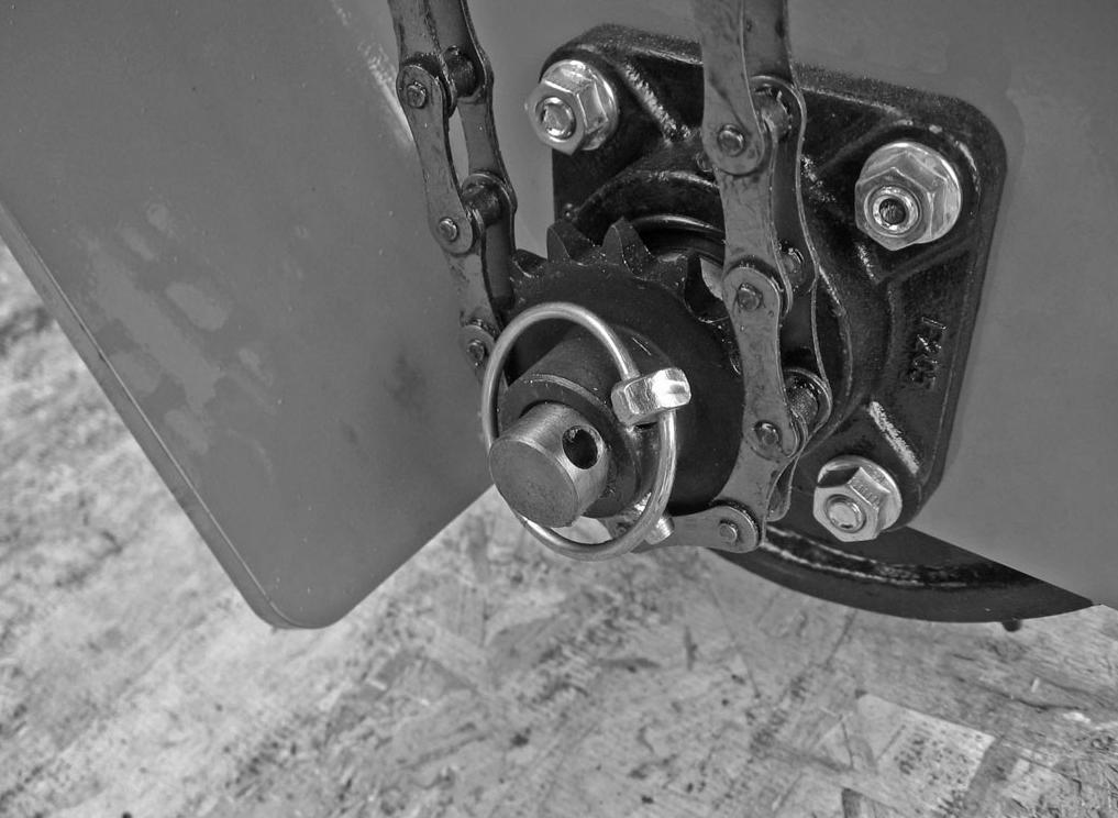
The Ground Seeder seed boxes can be engaged or disengaged so that any one seed box or all seed boxes can be operative or inoperative. See Figure 12 and Figure 25 for disconnect locations. It is not recommended to run the plastic seed cup assemblies without seed being metered.
It may be necessary to make several passes with the ground engaging tools before planting seed. Disengaging the seed box chain driv e will allow the soil bed to be prepared without planting seed or running the plastic seed cup assemblies in a dry state.
Operation
The power for operating the seeder comes from contact between the seeder rear roller and the turf.
■ Know how to stop the tractor and seeder quickly in an emergency.
NOTICE: Survey the area to be worked and remove any obstructions that may affect the performance of the equipment.
Seeding Operation
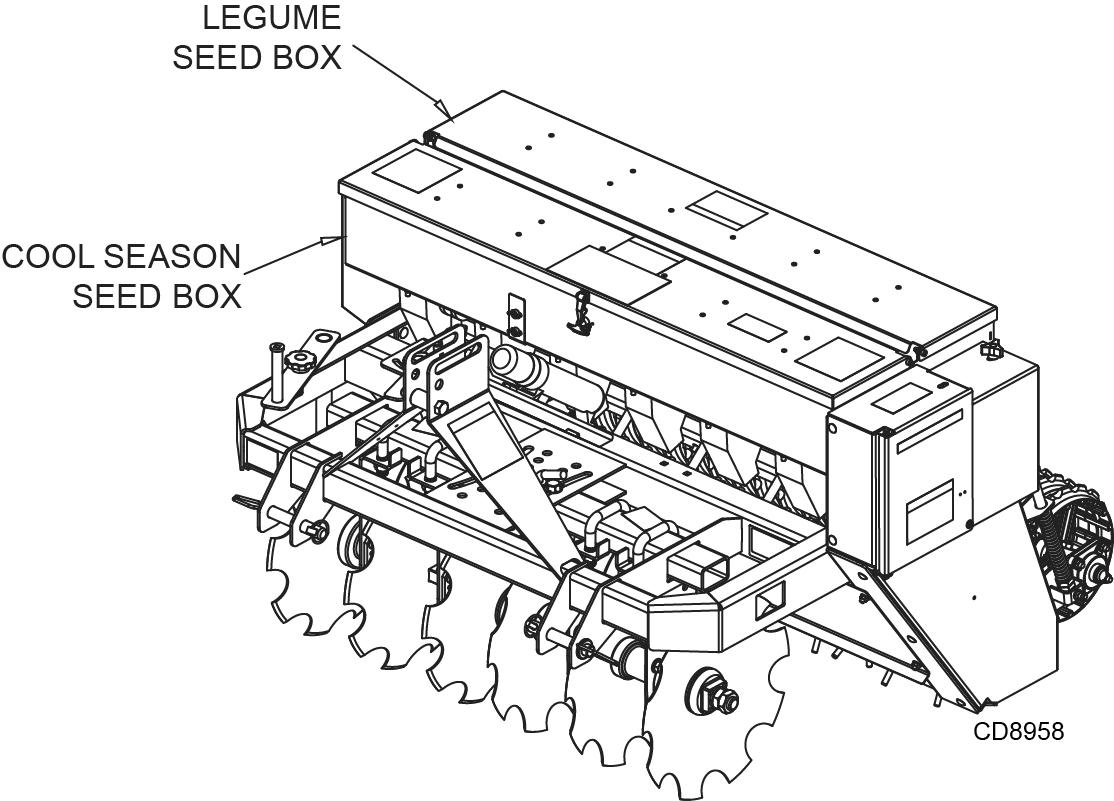
The Ground Seeder is capable of planting a wide variety of seeds over a wide range of seeding rates. The Ground Seeder is available with up to two different seed boxes. To determine which seed box is best for seeding, the size of the seed, planting depth and shape of the seed need to be considered.
The Cool Season seed box has a fluted roller seed cup with an adjustable concave. The seed cup is capable of planting large seeds including soybeans, grass seeds, as well as small legume seeds. The seed cup metering is adjustable with a common shaft and lever. As the seed shaft is moved axially more or less of the fluted seed roller is exposed changing the seed metering. See Figure 17. Additional rates can be achieved by changing the drive sprocket. The concave will need to be opened as the size of the seed increases. Opening the concave even further will also increase the seed rate. Seed from the Cool Season seed box is dropped on the divider and front seed tray. The roller then pushes the seed and soil down creating a firm seed bed with optimal seed to soil contact. See Figure 15.
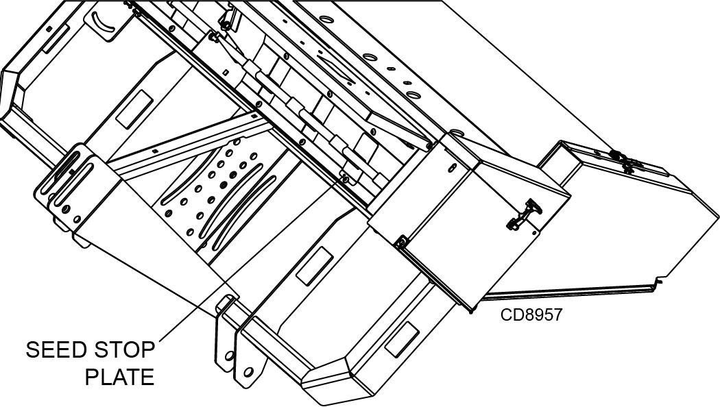
Seed stop plates, 5WP103865 8, shown in Figure 13, are available as an accessory to increase row width/reduce seeding rate. Place the seed stop plate over the seed cup hole as shown. The shape of the plate creates a tight fit.
The Legume seed box has a small seed cup and adjustable fluted roller. The lever and shaft are adjustable similarly to the Cool Season seed box. See Figure 20. The Legume seed box is ideal for planting alfalfa, clover, forbes, rape and other small seeds. The seed meter tubes attached to the Legume box can divert seed to the Cool Season transition tray for a deeper planting depth or in front of the optional cultipacker for shallower depths. See Figure 15.
Seed Box / Types of Seeds
Cool Season: Annual Rye Grass, Barley, Kentucky Blue Grass Blends, Fescue, Oats, Orchard Grass, Perennial Rye Grass, Snow Peas, Sorghum, Soybeans, Sunflower, Sudan, Wheat
Legume: Alfalfa, Bahai, Bermuda, Birdsfoot Tree Foil, Brassica, Buckwheat, Carpet Grass, Centipede Grass, Chicory, Clover, Fescue, Forb, Kentucky Blue Grass, Radishes, Rape, Sudan, Switch Grass, Timothy, Turnip
Important
■ Do not operate seeder in reverse. Operating seeder in reverse may result in damage to seed boxes and chain drive system.