2 minute read
OWNER SERVICE


Keep hands and body away from pressurized lines. Use paper or cardboard, not hands or other body parts to check for leaks. Wear safety goggles. Hydraulic fluid under pressure can easily penetrate skin and will cause serious injury or death.
NEVER GO UNDERNEATH EQUIPMENT. Never place any part of the body underneath equipment or between moveable parts even when engine has been turned off. Hydraulic system leak-down, hydraulic system failures, or movement of control levers can cause equipment to drop or rotate unexpectedly and cause severe injury or death.
Service work does not require going underneath implement.
Read Operator’s Manual for service instructions or have service performed by a qualified dealer. Never perform service or maintenance with engine running.
Before leaving Operator’s seat, follow power unit manual instructions. Lower loader arms and put attachment on the ground. Engage brake, stop engine, remove key, and remove seat belt.
Keep all persons away from operator control area while performing adjustments, service, or maintenance.
Your dealer can supply original equipment hydraulic accessories and repair parts. Substitute parts may not meet original equipment specifications and may be dangerous.
Lubrication
Do not let excess grease collect on or around parts. See Figure 9 for lubrication points and frequency for lubrication based on normal operating conditions. Severe or unusual conditions may require more frequent lubrication.
Use a lithium grease of #2 consistency with a MOLY (molybdenum disulfide) additive for all locations. Be sure to clean fittings thoroughly before attaching grease gun. One good pump of most guns is sufficient when lubrication schedule is followed.
Always wear relatively tight and belted clothing to avoid getting caught in moving parts. Wear sturdy, rough-soled work shoes and protective equipment for eyes, hair, hands, hearing, and head; and respirator or filter mask where appropriate.
Blade Cutting Edge Replacement
To reverse the cutting edge:
1. Remove the 1/2” carriage bolts.
2. Remove the cutting edge from the moldboard and reinstall with the sharp edge down.
3. Replace cutting edge when both edges are worn.
5WPMAN1182 (9/1/2016)
1.Blade
2.Moldboard Trip
BOLTS & PINS
Points
1. Check bolts and pins periodically to be sure they are tight.
2. Replace as necessary.
Cleaning
After Each Use
● Remove large debris from Front Blade.
● Inspect Front Blade and replace worn or damaged parts.
● Replace any safety decals that are missing or not readable.
Periodically or Before Extended Storage
● Clean large debris from Front Blade.
● Remove the remainder using a low-pressure water spray.
1. Be careful when spraying near scratched or torn safety decals or near edges of decals as water spray can peel decal off surface.
2. Be careful when spraying near chipped or scratched paint as water spray can lift paint.
3. If a pressure washer is used, follow the advice of the pressure washer manufacturer.
● Inspect Front Blade and replace worn or damaged parts.
● Sand down scratches and the edges of areas of missing paint and coat with spray paint of matching color (Purchased from your dealer).
● Replace any safety decals that are missing or not readable (supplied free by your dealer). See Safety Decals section for location drawing.
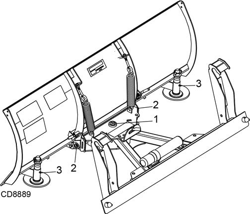
Trip Springs
(See Figure 10)
Two springs are installed on each Front Blade. These springs hold the blade in operating position and allow the blade to “trip” if an obstruction is encountered.
Normal installed spring length is 9” (inside hooks). If blade trips too easily, tighten spring adjustment eyebolts until performance is satisfactory. Do not exceed 9-5/8” spring length. Adjustments can be made to the trip springs by following these instructions:
1. Start tractor engine, release parking brake and/or place transmission in Neutral.
2. Fully lower loader arms to rest cutting edge on level ground.
3. Engage tractor parking brake and/or place transmission in Park. Shut off tractor engine and remove key.
4. Loosen jam nut (1) on lower side of eyebolt (2).
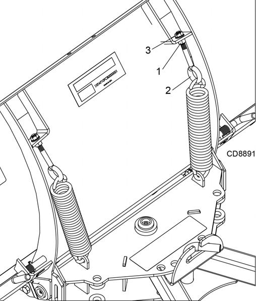
5. Tighten lock nut (3) on upper side of eyebolt to increase tension on trip spring. Loosen lock nut to reduce tension.
6. Tighten jam nut on lower side of eyebolt to secure adjustment.
7. Repeat trip spring adjustment for both sides and always adjust both springs equally.