8 minute read
OPERATION


The operator is responsible for the safe operation of this equipment. Operators must be instructed in and be capable of the safe operation of the equipment, its attachments and all controls. Do not allow anyone to operate this equipment without proper instructions.
The AF10F loader mounted Front Blade is designed for snow removal but may be used for spreading, leveling, or moving light material. The blade may be angled to windrow material for removal.
Optional accessory kits are also available for the AF10F Front Blade and are included in this manual. Non-marking, urethane cutting edge and skid shoes are designed to protect decorative driveway or patios. plow guides are available for increased visibility of the corners of the blade, and a rubber deflector is available to reduce material flow over the top of the moldboard during operation. The optional Hydraulic Adjustment Kit makes blade angle changes quicker and easier without leaving the tractor seat.
Always wear relatively tight and belted clothing to avoid getting caught in moving parts. Wear sturdy, rough-soled work shoes and protective equipment for eyes, hair, hands, hearing, and head; and respirator or filter mask where appropriate.
Stop power unit and equipment immediately upon striking an obstruction. Turn off engine, set parking brake, remove key, inspect, and repair any damage before resuming operation.
Air in hydraulic systems can cause erratic operation and allows loads or equipment components to drop unexpectedly. When connecting equipment or hoses or performing any hydraulic maintenance, purge any air in hydraulic system by operating all hydraulic functions several times. Do this before putting into service or allowing anyone to approach the equipment.
Never allow children or untrained persons to operate equipment.
Do not allow bystanders in the area when operating, attaching, removing, assembling, or servicing equipment.
Never allow riders on power unit or attachment. Keep all persons away from operator control area while performing adjustments, service, or maintenance.
Make sure that all operating and service personnel know that if hydraulic fluid penetrates skin, it must be surgically removed as soon as possible by a doctor familiar with this form of injury or gangrene, serious injury, or death will result.
CONTACT A PHYSICIAN IMMEDIATELY IF FLUID ENTERS SKIN OR EYES. DO NOT DELAY.
A minimum 20% of tractor and equipment weight must be on the tractor front wheels when attachments are in transport position. Without this weight, front tractor wheels could raise up resulting in loss of steering. Make sure the proper type and amount of ballast is used for machine stability. See Preparing the Tractor section of the loader Operator’s Manual for ballast requirements. Weigh the tractor and equipment. Do not estimate.
Make sure all hydraulic hoses, fittings, and valves are in good condition and not leaking before starting power unit or using equipment. Check and route hoses carefully to prevent damage. Hoses must not be twisted, bent sharply, kinked, frayed, pinched, or come into contact with any moving parts. Operate moveable components through full operational range to check clearances. Replace any damaged hoses immediately.
To help prevent injury from escaping hydraulic oil under pressure, relieve hydraulic system pressure before connecting or disconnecting hydraulic lines. See Relieving Pressure section of the Tractor Owner’s Manual for further instructions.
After connecting hoses, check that all control lever positions function as instructed in the Operator's Manual. Do not put into service until control lever and equipment movements are correct.
Ensure tractor hydraulic relief valve is set at no higher than 2500 psi (170 bars) (17,000 kPa) to prevent injury and equipment damage due to hydraulic system failure.
Make sure attachment is properly secured, adjusted, and in good operating condition. Attachment hooks must be secured on holders and attachment pins must be secured on holder straps with quick-lock pins.
PRE-OPERATION CHECK LIST
___Check that all hardware is properly installed and secured.
___Do not allow riders.
___Review and follow all safety rules and safety decal instructions on page 5 through page 8.
___Check that equipment is properly and securely attached to tractor.
___Make sure tractor ROPS or ROPS CAB and seat belt are in good condition. Keep seat belt securely fastened during operation.
___Check that all safety decals are installed and in good condition. Replace if needed.
Attach And Detach Front Blade To Loader
This Front Blade should only be mounted on tractor series specified on page 3 of this manual. Do not exceed maximum engine horsepower rating or tractor weight specified.
The AF10F Front Blade is shipped completely assembled and should only be installed on properly ballasted tractors equipped with the appropriate loader.
John Deere Quik-Tach
(See Figure 1)
1. Start tractor engine, release parking brake and/or place transmission in Neutral.
2. Roll Front Blade back slightly and raise boom approximately 18" above ground level.
3. Engage tractor parking brake and/or place transmission in Park. Shut off tractor engine and remove key.
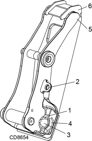
4. Remove quick-lock pin (1) from each side of the Front Blade and store pins in storage position (2).
5. Start tractor engine. Extend bucket cylinders until the Front Blade pin (3) releases from holder strap (4) on each side of the Front Blade.
6. Lower loader boom, place transmission in Reverse and move away from the Front Blade. Holder (5) will release from hook (6) on each side of attachment.
7. Set parking brake and/or place transmission in Park. Shut off tractor engine and remove key.
8. Attach the Front Blade in reverse order of detaching.
Hydraulic Angle Kit (if equipped)
(See Figure 2)
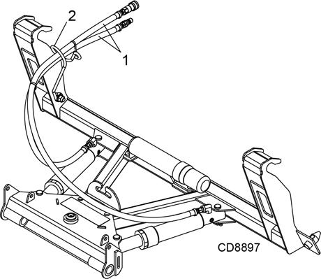
Connecting Hydraulic Hoses
1. Lower Front Blade to the ground.
2. Relieve pressure in the 3rd function auxiliary circuit. (See Tractor Operator’s Manual.)
3. Set parking brake and/or place transmission in Park. Shut off tractor engine and remove key.
4. Make sure hydraulic hoses (1) are routed through the hose holder (2).
5. Connect the Front Blade’s hydraulic pressure lines to the tractor loader 3rd function auxiliary circuit. NOTE: Hose connections are identified with alternating male and female quick connect fittings to ensure hoses are matched correctly to the quick connect fittings on the 3rd function auxiliary circuit.
Disconnecting Hydraulic Hoses
1. Lower Front Blade to the ground.
2. Relieve pressure in the 3rd function auxiliary circuit. (See Tractor Operator’s Manual.)
3. Set parking brake and/or place transmission in Park. Shut off tractor engine and remove key.
4. Disconnect the Front Blade’s hydraulic pressure lines from the tractor loader 3rd function auxiliary circuit.
5. Couple the Front Blade’s hydraulic pressure lines together when not in use to keep the quick connect fittings clean and protected.
Adjustment
Before manually changing positions of blade angle or skid shoes: Park tractor on level ground, apply parking brake, level implement boom, shut off tractor, and remove key.
Make manual changes slowly and carefully to prevent hazardous movement of mechanisms. Never stand in positions where you could become entrapped during adjustment changes or if the loader suddenly lowers. Ensure joystick is lock ed during all adjustments for blade or skid shoes.
For manual adjustment blades, always secure angle lock pin to one side to prevent lock pin from bumping out of the positioning holes. Failure to do so may result in accidents and/or damage to the Front Blade.
For hydraulic adjustment blades, ensure angle lock pin is removed. Failure to do so may result in accidents and/or damage to the Front Blade.
Blade Angle Adjustment - Manual
(See Figure 3)
The Front Blade angle may be adjusted to the center and 15° or 30° to the right or left of center. Blade angle should be adjusted by the operator as desired for windrowing material for removal.
1. Start tractor engine, release parking brake and/or place transmission in Neutral.
2. Roll Front Blade to level position and lower boom until skid shoes contact ground. Raise boom until skid shoes clear ground and lock joystick.
3. Engage tractor parking brake and/or place transmission in Park. Shut off tractor engine and remove key.
4. Remove angle lock pin (1) from storage position.
5. Set blade to desired angle position. 0, 15° or 30° right or left.
6. Replace lock pin and secure to one side.
Blade Angle Adjustment - Hydraulic
(See Figure 3)
The Front Blade may be angled up to 30°, or to any position in between, right or left of center, by hydraulic remote control from the tractor seat.To prevent damage to the Front Blade and hydraulic cylinders, make sure to remove lock pin (1).
1. Raise the Front Blade a couple of inches off the ground by operating the control lever of the tractor loader.
2. Actuate the loader 3rd function control valve until the desired angle adjustment is reached.
NOTE: Do not angle the Front Blade under load.
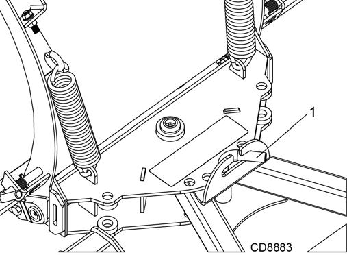
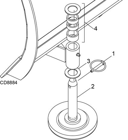
Skid Shoes
(See Figure 4)
Skid shoes are used to provide height control and to help prevent gouging. Skid shoes should be adjusted by the operator for the type of surface to be cleaned.
1. Start tractor engine, release parking brake and/or place transmission in Neutral.
2. Roll Front Blade to level position and lower boom until skid shoes contact ground. Raise boom until skid shoes clear ground.
3. Lower loader arms to rest cutting edge on two 4" x 4" blocks and lock joystick. Place blocks so that they are solidly positioned and stable. Do not place any part of the body beneath the raised Front Blade when making adjustments.
4. Engage tractor parking brake and/or place transmission in Park. Shut off tractor engine and remove key.
5. Remove lock pin (1) from skid shoe (2) and remove skid shoe. (Rev.
5WPMAN1182 (9/1/2016)
6. To lower blade height, remove spacers (as necessary) from the spacer stack (3). Re-install skid shoe in support bracket and place all removed spacers under lock pin for storage (4). Re-install lock pin.
7. To raise blade height, remove spacers (as necessary) from storage under lock pin and place in spacer stack. Re-install lock pin.
8. Repeat skid shoe adjustment for both sides and adjust both skid shoes equally.
Light Material
The Front Blade may be used for spreading, leveling or moving light materials. The blade should not be used for dozing undisturbed soil or heavy materials as this may result in damage to the Front Blade.
Transportation
Moldboard Lock
(See Figure 5)
The Front Blade comes equipped with moldboard lock pins to secure the moldboard during transportation. Both moldboard lock pins should be engaged for transportation and both disengaged for operation.
1. Start tractor engine, release parking brake and/or place transmission in neutral.
2. Roll Front Blade to level position and lower boom until skid shoes contact ground. Raise boom until skid shoes clear ground and lock joystick.
3. Engage tractor parking brake and/or place transmission in Park. Shut off tractor engine and remove key.
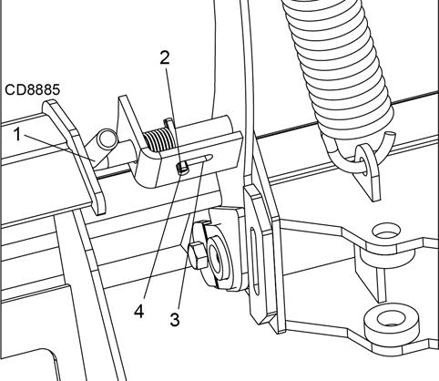
4. Engage lock pin (1) for transportation by pulling out and rotating until spring pin (2) is aligned with the locked position (3). Release lock pin to engage into moldboard. Repeat on other side.
Operating
The Front Blade should operating with the frame parallel to the ground with the attachment coupler rotated forward. Level the Front Blade with the Loader level indicator that has been properly adjusted for parallel operation.
■ Always inspect area and locate obstructions prior to Front Blade operation.
■ Dozing undisturbed soil or heavy material may result in damage to the Front Blade.
Snow Removal
The Front Blade is to be used for snow removal from hard level surfaces. The moldboard is designed to trip forward if an obstruction is encountered during operation. Optional urethane cutting edge and skid shoes are offered and should be used to protect decorative driveways and patios.
5. Disengage lock pins for operation by pulling outward on lock pin then rotating until spring pin is secured in the storage position (4). Repeat on other side.