
10 minute read
Section 3: Machine Operation


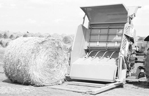
3.1Introduction to the machine
3.1.2Operator’s station/controls
Operator controlled items:
•Loading tines, to load the bale. One tractor hydraulic circuit is used to control loading tines. (See section 3.2.6 for more information.)
•The PTO shaft, which runs the rotor.
•The bale conveyor chain. Another tractor hydraulic circuit is used to control the bale conveyor’s speed and direction. If the tractor is equipped with a PFC circuit, use it to control the bale conveyor.
Adjustable items:
•The conveyor speed control valve (See section 3.4.2 for more information.)
•Slug bar setting (See section 3.4.2 for more information.)
•Deflector settings (See section 3.4.1 for more information.)
3.1.3Bale conveyor speed
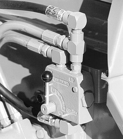
Bale conveyor speed is set with the bale conveyor speed control valve. To chop the forage finer, decrease the conveyor speed by rotating the control lever up and to the left. For a coarser cut, increase the conveyor speed by rotating the lever to the right and down.
3.1.4Deflector
speed control valve
The deflector can be positioned for creating a windrow, spreading, bunkfeeding, or stockpiling. Lower the deflector for a narrower windrow and raise the deflector for a wider spread.
To change the position, squeeze the deflector release lever into the deflector latch handle. Rotate the deflector to the desired position and release. A wider deflector belt (PN 5HB8100819) is available for bunk feeding or additional material control.
3.1.5Stripper plates/screens
The BP 1166 BALE PROCESSOR comes with one stripper plate standard. For a finer cut, one or two more stripper plates can be added. (See section 3.4.2, for more information about adding or removing stripper plates.)
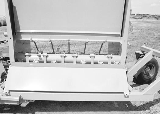
In applications where a very coarse cut is desired, the stripper plate may be removed.
3.1.6Rotor
The rotor flails shred the bale and throws the material into the deflector. Rotor speed should remain constant, which is done by keeping the tractor PTO at 1000 RPM.
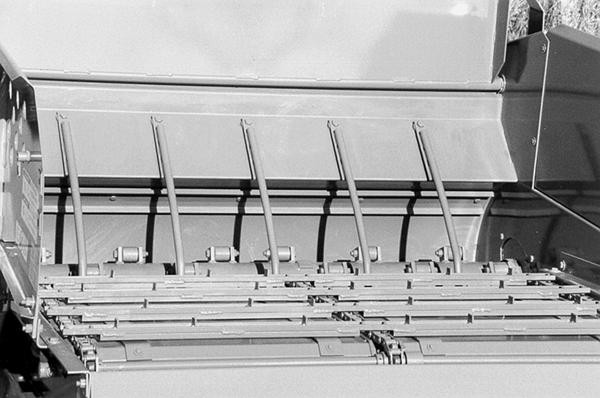
3.1.7 Slug bars
The BP1166 BALE PROCESSOR comes with five slug bars.
The slug bars can also be adjusted to expose more or less of the flail knives to the bale. This is accomplished by adding and subtracting flat washers, from either end of each bar.
Operating tractor at maximum RPM allows machine to do a better job of chopping forage, and also minimizes twine buildup on the rotor. Twine buildup should be kept to a minimum to reduce fire hazard.
WARNING: SERIOUS INJURY COULD RESULT IF MACHINE IS ALLOWED TO TIP. Basic machine is equipped with two (2) stands for storage. Make sure base of stands are setting firmly before unhooking from tractor mounts. Always operate slat conveyor to rotate bale in direction indicated by arrow on front shield. Reverse the direction of rotation only if bale is lodged or hesitates to turn.
3.1.8Rotor access door
3.2 Operation
To insure long life and economical operation, we highly recommend the operator of the BP1166 BALE PROCESSOR be thoroughly instructed in the maintenance and operation of the machine. There is no substitute for a sound preventative maintenance program and a well-trained operator.
Prior to starting the engine of the tractor, we recommend the operator make a visual inspection of the unit. This can be done as the lubrication is being carried out. Any items that are worn, broken, missing or needing adjustment must be serviced accordingly before operating the BP1166 BALE PROCESSOR.
3.2.1 Pre-operation inspection
WARNING: Before inspecting the machine, use the normal shutdown procedure in section 3.2.4.
Check the following:
Condition of flails and attachment bolts.
Rotor for twine build-up.
Chains for proper tension, and condition.
Check for loose bolts, worn or broken parts.
All lubrication points have been serviced.
Lug nuts for tightness.
Condition of tire rims.
Tires for proper air pressure.
Installation of slow moving vehicle (SMV) sign if required.
Installation and condition of shields.
Condition of decals.
Hydraulic components for leaks or damage.
Check for loose flail anchor bolts, torque to 200 Ft lbs.
WARNING: Hydraulic fluid escaping under pressure can be almost invisible and can have sufficient force to penetrate the skin. When searching for suspected leaks, use a piece of wood or cardboard rather than your hands. If injured, seek medical attention immediately to prevent serious infection or reaction.
Test run the BP1166 BALE PROCESSOR before loading. To prevent damaging the BP1166 BALE PROCESSOR always engage PTO with engine idling. Look for excessive vibration, loose or broken parts. Make any necessary repairs before attempting to do any bale feeding.
3.2.2Hitching the BP1166 BALE PROCESSOR to a tractor
To hitch the BP1166 BALE PROCESSOR to a tractor, perform the following steps:
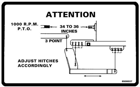
1.These settings must be made to the tractor’s 3-pt hitch prior to operating the BP1166 BALE PROCESSOR.
A.Eliminate the 3-pt hitch side-to-side movement by installing or setting the sway blocks for the rigid operation.
B.Eliminate lower link mechanical flotation by setting it to the rigid position.
C.See the operator’s manual or your tractor’s dealer for precise instructions.
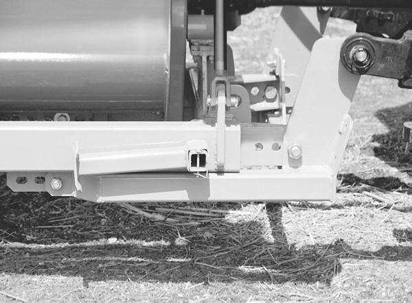
2.Measure the distance between the end of the PTO shaft and the end of the rotor shaft. The distance should be 34-36 inches.
NOTE: If distance is not 34-36 inches, follow steps 3-5.
3.Detach the tractor from the BP1166 BALE PROCESSOR.
4.Reinstall the adjustable hitches in any of the four holes on the main frame so that the 34 to 36 inch measurement will be obtained when the tractor is attached.
5.Reattach the tractor to the BP1166 BALE PROCESSOR.
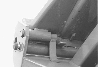
6.Attach the PTO shaft to the tractor PTO shaft. Depress the button on the coupling and slide the coupling onto the splined shaft. Make sure the spring loaded safety catch is properly seated.
7.Connect the two hydraulic hoses from the hydraulic cylinder to one set of hydraulic couplers on the tractor.
8.Connect the two hydraulic hoses from the bale conveyor speed control valve to the second set of hydraulic couplers on the tractor.
9.Raise the three point hitch until the BP1166 BALE PROCESSOR frame is level. Lock the hitch control
10.Remove pin on jackstands, and then turn jackstands 90° and use the pin to reinstall the jackstands on the bracket. (See Figure 3.5)
NOTE: The use of stabilizers or sway bars is recommended to prevent sideways movement of the machine.
IMPORTANT: When using smaller tractors in the CATEGORY III class, be certain three-point rating is at least 4000 Ibs.
WARNING: Improper hitch adjustment may cause separation of P.T.O., driveline when loading bale or operating over uneven terrain. Separation may also occur if three point links are lifted excessively high.
3.2.3Starting the machine
With Tractor hooked up to the BP1166 BALE PROCESSOR, try all functions on the machine.
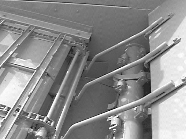
1.To unfold rack and deflector, loader tine frame: a. Place the tine frame pin in the unlocked position. b. When unfolding, keep bystanders away from the work area. c. Start the engine; tilt hinge frame hydraulically to allow the loader tine frame to be unfolded and lay on ground. d. Lock tine frame pin into working position. e. Tilt hinge frame hydraulically to working position. f. Unlock rack strap. Fold out rack and deflector. Lock into working position.
2.Adjust the deflector.
With the engine at idle:
1.Raise and lower the loading tines.
2.Engage the bale conveyor, and adjust conveyor speed control valve on the BP1166 BALE PROCESSOR.
3.Engage the tractor PTO, and the rotor should start turning. Listen for any odd noises and vibrations.
WARNING: After making all necessary hook-ups to tractor, be sure rotor chamber is clear of any solid objects. Make sure any bystanders are away from discharge before engaging PTO. Flying objects can cause serious injury or even death. Stay clear of discharge side of machine unless operator has stopped tractor engine and machine has stopped rotating. Failure to follow these instructions may result in severe injury.
To start the machine, perform the following steps:
1.Adjust the deflector to desired position.
2.Load bale into the BP1166 BALE PROCESSOR. (See Section 3.2.6 for a description of this procedure.)
3.Position the BP1166 BALE PROCESSOR where you want to begin shredding the bale.
4.Engage the PTO, and increase tractor engine speed so PTO is at 1000 RPM.
5.Engage the bale conveyor, and check to see if the bale is turning in the right direction. The proper direction of bale rotation is indicated by the bale rotation decal located on the front of the BP1166 BALE PROCESSOR.
NOTE: Operating tractor PTO at 1000 RPM allows machine to do a better job of chopping forage and also keeps a minimum of twine build-up on the rotor. Twine build-up should be kept to a minimum to reduce fire hazard.
NOTE: Operate bale conveyor to rotate the bale in direction indicated by arrow on the front shield. Reverse direction only if the bale is lodged or hesitates to turn.
CAUTION: Serious injury could result if machine is allowed to tip.
3.2.4Normal shut-down procedure
WARNING: For your safety and the safety of others, you must use the following normal shut-down procedure before leaving the tractor controls unattended for any reason, including servicing, cleaning, or inspecting the BP1166 BALE PROCESSOR. A variation of the following procedure may be used if so instructed within this manual or your tractor manual or if an extreme emergency requires it.
To shutdown the machine, perform the following steps:
1.Shut hydraulic drive off for chain conveyor.
2.Disengage PTO
3.Lower machine to ground level.
4.Place transmission in park or set park brake
5.Shut Off engine and remove key.
6.Wait for all movement to stop.
3.2.5Unhitching the BP1166 BALE PROCESSOR from a tractor
To unhitch the BP1166 BALE PROCESSOR from a tractor, perform the following steps:
1.Run the BP1166 BALE PROCESSOR until it is empty.
2.Shut-down the BP1166 BALE PROCESSOR as described above, keeping the BP1166 BALE PROCESSOR high enough to allow adjustment and lowering of the jackstands.
3.Remove the jackstand and pins, and turn jackstands 90° so that the machine can be supported by the jackstands. Reinstall the jackstands and pins on their brackets.
4.Lower machine until the BP1166 BALE PROCESSOR rests on both jackstands.
5.Disconnect the hydraulic hoses from the tractor.
6.Disconnect the PTO from the tractor, and place the front half of the shaft into the bracket located on the front of the BP1166 BALE PROCESSOR.
7.Disconnect the tractor lift arms from the BP1166 BALE PROCESSOR.
8.Drive the tractor slowly away from the BP1166 BALE PROCESSOR.
3.2.6 Loading bales into the BP1166 BALE PROCESSOR
To load bales into the BP1166 BALE PROCESSO R, perform the following steps:
NOTE: The loading area should be flat and level.
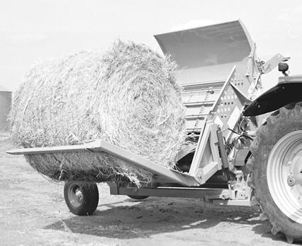
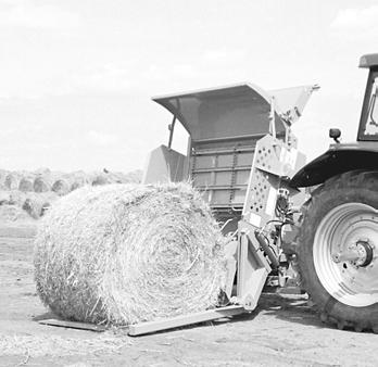
1.Position the BP1166 BALE PROCESSOR ahead and to the side of the bale. Extend the hydraulic cylinder, lowering the loading tines until they are on the ground.
2.Back up slowly, while centering the bale between the tines. Back up until the loader frame touches the front of the bale.
3.Retract the hydraulic cylinder slowly. The bale will roll into the shredding chamber.
4.Once the cylinder is completely retracted, the BP1166 BALE PROCESSOR is ready to shred the bale.
3.3Transportation and storage
This machine is designed to fold for ease of transportation and storage.
1. To fold rack and deflector, loader and tine frame: a.Raise the deflector to it’s highest position. b.Unlock rock strap. Fold rack and deflector into chamber. c.Tilt hinge frame hydraulically to allow loader tine frame to be folded into transport position. Lock tine frame pin in transport position. d.Tilt hinge frame hydraulically into transport/storage position.
2.Use good judgment and drive slowly over rough or uneven terrain.
3.Be sure tractor brakes are properly adjusted and foot pedals are locked together.
4.Check your state laws regarding the use of lights, slow moving vehicle signs, safety chain and other possible requirements.
NOTE: A bracket is located on the front of the BP1166 BALE PROCESSOR to hold the front half of the PTO shaft.
3.3.1Preparing for storage
WARNING: When preparing machine for storage, use normal shutdown procedure.
Clean all mud, dirt, grease and other foreign material from the exterior of the machine. Cut all twine off from around the rotor. Wash the complete machine. If washing the BP1166 BALE PROCESSOR with a high-pressure washer, keep the nozzle away from the sealed bearings. Repaint places where bare metal is exposed - this will inhibit rusting.
Place the parking stands in the down and in locked position. Block the rear axle up taking the weight off the tires, but do not deflate the tires. If possible, store the machine in a dry, protected place. If it is nessecery to store the machine outside, cover it with waterproff canvas, plastic, or other suitible protective material.
Check the machine for any worn or broken parts. By ordering parts now, you will avoid delays when it is time to Check Coat exposed lift cylinder rod with grease. Oil chains on conveyor. Lubricate thoroughly according to lubrication instructions. Repack wheel bearings.Check the machine for broken parts. By ordering parts now, you will avoid delays when it is time to remove the machine from storage. When ordering parts always specify machine serial number and the part number of the replacement part. Part numbers can be found in the parts section of this manual.
3.3.2Removing from storage (shipping position)
1. Remove all protective coverings.
2.Remove blocking from under BP1166 BALE PROCESSOR. Check tire pressure.
3.Lubricate machine in accordance with lubrication instructions found in this manual.
4.Check all hydraulic hoses for deterioration and, if necessary, replace. Tighten any loose bolts, nuts and hydraulic fittings.
5.Follow pre-starting inspection instructions.
3.4Adjusting the machine
3.4.1Changing distribution pattern
The deflector can be positioned for creating a windrow, spreading, bunkfeeding, or stockpiling. Lower the deflector for a narrower windrow and raise the deflector for a wider spread.
To change the position, pull the release lever, Rotate the deflector to the desired position and release the handle. A wider deflector belt (PN 5HB8100819) is available for bunk feeding or additional material control.
3.4.2Changing length of cut
Changing Stripper Plates
Adding stripper plates will produce a finer cut and removing plates will produce a coarser cut. (See Figure 3.7 and section 3.1.5)
For a finer cut, one or two more stripper plates can be added. Space the added stripper plates 4” apart and drill five (5) 17/32” holes for each plate using the plate as a guide. Install the plate with five 1/2” x 1-1/2” bolts, flat washers, lock washers, and nuts.
In applications such as land reclamation, where a very coarse cut is desired, the stripper plate may be removed.
Changing Slug Bar Settings
Exposing less flail will create a finer cut, while exposing more flail will create a coarser cut. This is accomplished by moving flat washers from one end of each bar to the other end.
Adjust Conveyor Speed
Moving the lever counterclockwise will slow the conveyor, and make a finer product. Moving the lever clockwise will speed up the conveyor and make a coarser product.
For tractors with PFC type hydraulic systems: speed control valve
This valve should be set in the full open position. Conveyor speed can be controlled directly from the tractor controls.