18 minute read
8, 9, 10, 11, 13, 15, and 18-Speed Troubleshooting


Symptom
• Air Leak at Shift Knob • Air Leak at Slave Valve • Air Leak from Transmission Breather or Transmission Case is Pressurized • Air Leak at Splitter Cylinder Cover Exhaust Port • No or Slow Range Shift into Low • No or Slow Range Shift into High • Range Shifts with Shift Lever in Gear
WARNING: Use care when removing air lines or checking for air flow from disconnected lines. High pressure air may exhaust suddenly. Wear safety glasses. Exhaust all air pressure from system before removing air filter/regulator or combination cylinder cover. Note: During all testing, the vehicle air pressure must be greater than 90 PSI (620 kPa). If during testing the pressure falls below 90 PSI (620 kPa), make sure the transmission is in neutral, start the engine, and let the pressure build to governor cutoff. After the pressure reaches the governor cutoff, continue testing. The pressure is critical if the vehicle is equipped with a Pressure Protection Valve that would shut off the air supply to certain air circuits if the system pressure dropped below a preset level.
IMPORTANT: Use the following air system troubleshooting procedures for part replacement only if the symptom can be duplicated. If the problem is intermittent, parts that are not defective could be replaced.
Instructions
1. Start at “Procedures” for Step A. 2. Based on the “Result” of the procedure, go to the corresponding “What To Do Next”.
Procedure 1: Symptom - Air Leak at Shift Knob
Normal Operation:
• A burst of air will be exhausted from the shift knob when moving the range selector from low to high. This is the air being exhausted from the “P” air line. • A burst of air will be exhausted from the shift knob when moving the splitter button rearward (shifting to low split). This is the air being exhausted from the “SP” air line.
Possible Causes:
• Incorrectly attached air lines • Internal leak in slave valve • Internal leak at insert valve • Internal leak at shift knob Table 10 Air Leak at Shift Knob
Procedure Result What to do next Step A Remove lower skirt on shift knob. Leak found. Repair leaking fitting or air line. Check for leaking fitting at the shift knob.
Step B Check air lines to make sure all lines are connected to the proper ports on the shift knob. A.) Reversal of “S” and “P” lines will result in a constant leak from the exhaust when high range is selected. B.) Reversal of the H/L and “SP” lines will result in a constant leak when the splitter button is rearward. Step C Move the range selector lever down to low range. Check for constant air flow from the exhaust “E” port.
Step D Move the range selector up to high range. Disconnect the small air line connected to the “P” port of the shift knob. Check for air flow from the port and air line. No leak found. Go to Step B. Air lines are not connected to the proper ports. Connect lines properly.
Air lines are connected to the proper ports. Go to Step C.
Constant air flow from the “E” port. Replace knob.
No air flow from “E” port. Go to Step D. Constant air is leaking from the “P” port or the “E” port. Repair or replace the shift knob.
Air is coming out of the disconnected air line.
Air is not leaking from either port or disconnected air line. 1. Verify that the air line is connected to the slave valve “p” port. 2. If properly connected, replace the slave valve. Go to Step E.
Table 10 Air Leak at Shift Knob
Procedure Result What to do next Step E Reattach the air line to the “P” port. Move the range selector down to low range and move the splitter button rearward. Disconnect line from the “SP” port. Check for air flowing from the SP port on the shift knob. Air is flowing from the SP line. 1. Check to make sure the “SP” line is connected to the splitter cylinder cover.
2. If the line is properly attached, check that the insert valve (old style) is properly installed (stem facing inward) and that the insert valve bore is not defective. 3. Replace the insert valve. Air is not flowing from the line. Repair or replace the shift knob.
Procedure 2: Symptom - Air Leak at Slave Valve
Normal Operation:
A momentary exhaust of air at the slave valve occurs during a range shift. The air from the low side of the range cylinder is exhausted as air pressure is applied to the high range side. Likewise, air from the high range side of the piston is exhausted as air pressure is applied to the low range side. The exhaust port is located at the slave valve to transmission mounting interface.
Possible Causes:
• Internal leak in range cylinder. • Internal leak in slave valve. Table 11 Air Leak at Slave Valve
Procedure Result What to do next Step A Confirm that air is leaking from the ex- Air is leaking from fitting or air line. Repair or replace fitting or air line. haust port on the slave valve and not a fitting or air line.
Air is definitely leaking from slave valve exhaust port. Go to Step B.
Step B Move range selector down to select low range. Remove the 1/4" I.D. rubber air line at the high range supply port on the range cylinder. Feel for air flow from the open port on the range cylinder. Notice if the air leak at the slave valve only occurs when the transmission is in high range. Repeat the above test but remove the low range air hose and check with high range selected. Air is flowing from high range supply port on range cylinder. Remove range cylinder cover and repair leaking range piston or piston seal. After repair, check for proper range operation.
No air flow from high range port. Repair or replace slave valve.
Normal Operation:
There should be no measurable air flow from the transmission breather.
Possible Causes:
• Leak at range yoke bar O-ring • Leak at splitter yoke bar O-ring Table 12 Air Leak from Transmission Breather or Transmission Case is Pressurized
Procedure Result What to do next Step A Listen for the air leak with the trans- Leak is only in low range. Remove range cylinder and inspect for mission shifted to both low and damaged range yoke bar, yoke bar Ohigh range. ring, or range cylinder. Repair as necessary.
Leak is in both low and highrange. Remove splitter cylinder. Inspect for damaged splitter yoke bar, O-ring, or cylinder. Repair as necessary.
Normal Operation:
A burst of air will exhaust from this port when shifting into low split (the splitter button is moved rearward while in low range).
Possible Causes:
• Damaged/defective insert valve • Leak past insert valve external O-rings • Leak past splitter cylinder piston Table 13 Air Leak at Splitter Cylinder Cover Exhaust Port
Procedure Result What to do next
Step A (old style) Remove insert valve. Check for contamination, damaged seals, or sticky movement. Check the insert valve bore in the splitter cylinder cover for contamination or damage which would result in leakage past the insert valve O-rings. Contamination or damage found.
No contamination or damage found. Repair or replace as necessary.
Go to Step B.
Step B Remove the splitter cylinder cover and piston. Check the piston bore for contamination or damage. Check the piston seals for damage. NOTE: Early production transmissions used a paper gasket to seal the splitter cover to cylinder, if necessary, replace this configuration with the spool valve design which uses an O-ring. Contamination or damage found. Repair or replace as necessary.
Normal Operation:
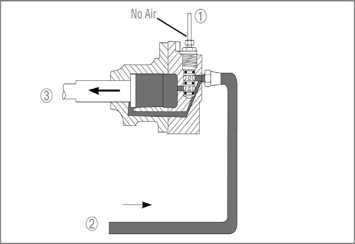
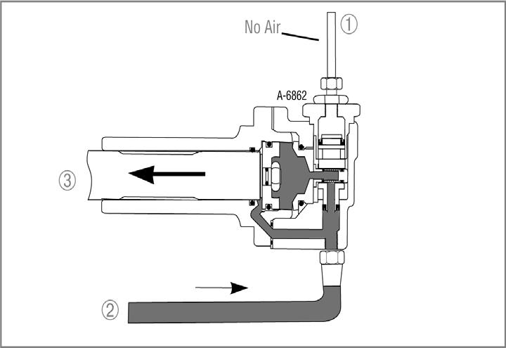
When the range selector on the shift knob is moved down to select low range, air pressure will flow through the shift knob to the "P" port on the slave valve. The slave valve will direct air pressure through the low range 1/4" rubber hose to the range cylinder to shift the range. There will be a brief burst of air at the slave valve as the high range side of the range piston exhausts. Likewise, when high range is selected, the air pressure in the "P" will be exhausted at the shift knob. This will cause the slave valve to direct air to the rear side of the range cylinder piston. The air pressure on the low range side will be exhausted at the slave valve.
Possible Causes:
• Incorrect air line hook up • Insufficient air supply to transmission • Damaged or defective air filter / regulator assembly • Damaged or defective shift knob master valve • Damaged or defective slave valve • Damaged or defective range cylinder • Damaged or defective range yoke or yoke bar • Damaged or defective range synchronizer • Damaged or defective gearing in auxiliary section of transmission Table 14 No or Slow Range Shift into Low
Procedure Result What to do next Step A Place the shift lever in neutral. Constant air leak is detected. Go to the other corresponding sympCheck for constant air leakage at the shift tom first. See beginning of Air System knob, slave valve, and transmission case Troubleshooting section. breather when both low and high range have been selected.
Step B Place shift lever in neutral. Move range selector up to high range position. At the rear of the transmission, disconnect the 1/4" rubber air line from the low range supply port on the range cylinder. Check for air flow from the low range port.
Step C Check for air flow from the disconnected air line. No constant leak is detected. Go to Step B. Air flows from the low range port. Remove range cylinder cover and repair leaking range piston or piston seal.
No air flow from low range port. Air flows from disconnected air line. Go to step C.
Go to step F.
No air flow from disconnected line. Go to step D.
Table 14 No or Slow Range Shift into Low
Procedure Result What to do next Step D Install a 100 PSI air gauge in the disconnected air line end. With the shift lever in neutral, move the range selector down to select low range. Observe the gauge.
Step E Confirm that shift lever is still in neutral. Have an assistant move the range selector up and down between low and high range. Does the pressure measured at the gauge respond rapidly when going from high to low?
Step F Place shift lever in neutral. At the shift knob, move the range selection lever up to select high range. At the slave valve, remove the air line from the "P" port. (should be a black line). Check for air flow from the disconnected line. The gauge read 0 PSI. Go to step F.
The gauge reads pressure but is lower than 58 PSI or higher than 63 PSI. The gauge reads between 58 63 PSI. Pressure rapidly changes between 58-63 PSI and 0 at the gauge. Replace the filter/regulator and check for proper range operation.
Go to step E.
Air system appears to be operating satisfactory. Go to step R.
Pressure does not change rapidly at gauge.
Air flows from the disconnected line. 1. Check for a plugged or dirty filter in the filter/regulator assembly. 2. Check for a pinched or obstructed 1/4" rubber air line between the filter/ regulator and slave valve. 3. Check for a pinched or obstructed 1/4" rubber air line between the slave valve and the test gauge. 4. If all are satisfactory, go to step F. 1. Confirm that the air lines are connected to the correct ports at the shift knob.
Step G Check for air flow from the "P" port on the slave valve. No air flow from the disconnected line. 2. If the lines are correct, replace the shift knob. Go to step G.
Air flows from this port. Replace the slave valve.
No air flow from this port. Go to step H.
Table 14 No or Slow Range Shift into Low
Procedure Result What to do next Step H Place the shift lever in neutral. Install a 100 PSI pressure gauge in line with the "P" line. Move the range selector back and forth from low to high range. The gauge should show rapid pressure change.
Step I If possible, leave air lines attached to slave valve. Unbolt the slave valve from transmission side. Check for free movement of the plunger pin protruding from the case under the slave valve. The pin should extract when the transmission is shifted into gear and retract when shifted into neutral. NOTE: If desired, the slave valve can be actuated and tested while unbolted from the transmission case. The air lines, of course, must remain attached. The gauge responds slowly. 1. Check for a restricted line between the shift knob and slave valve.
The gauge rapidly moves between 58-63 PSI and 0 PSI. Actuating plunger pin does not move freely. 2. If the lines are correct, replace the shift knob. 3. Check for a plugged or dirty filter in the filter / regulator assembly. 4. Check for a pinched or obstructed 1/4" rubber air line between the filter/ regulator and slave valve. 5. Check for a pinched or obstructed air line between the slave valve and the "S" port on the shift knob. 6. If all are good, replace the shift knob. Go to step I.
1. Remove actuating plunger pin and check for damage.
Actuating plunger pin moves freely. 2. Check for missing or broken spring. Repair or replace slave valve and check for proper range operation.
Table 14 No or Slow Range Shift into Low
Procedure Result What to do next Step R If air system has been tested and found to operate satisfactory, the auxiliary section must be removed to inspect for mechanical problem. Remove auxiliary section and inspect for: •Binding of range yoke bar or piston •Damaged or defective range yoke •Damaged or defective range synchronizer •Cracked countershaft weld resulting in gear turning on shaft •Damaged or defective range sliding clutch •Auxiliary section gearing out of time
Normal Operation:
When the range selector on the shift knob is moved down to select low range, air pressure will flow through the shift knob to the 'P" port on the slave valve. The slave valve will direct air pressure through the low range 1/4" rubber supply hose to the range cylinder to shift the range. There will be a brief burst of air at the slave valve as the high range side of the range piston exhausts.
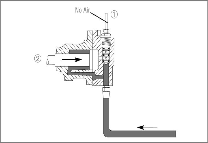
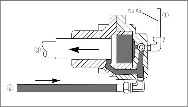
Likewise, when high range is selected, the air pressure in the "P" will be exhausted at the shift knob. This will cause the slave valve to direct air to the rear side of the range cylinder piston. The air pressure on the low range side will be exhausted at the slave valve.
Possible Causes:
• Incorrect air line hook up • Insufficient air supply to transmission • Plugged filter • Incorrect regulator pressure • Damaged or defective shift knob master valve • Damaged or defective slave valve • Damaged or defective range cylinder • Damaged or defective range yoke or yoke bar • Damaged or defective range synchronizer • Damaged or defective gearing in auxiliary section of transmission Table 15 No or Slow Range Shift into High
Procedure Result What to do next Step A Place the shift lever in neutral. Constant air leak is detected. Go to the other corresponding sympCheck for constant air leakage at the shift tom first. See beginning of Air System knob, slave valve, and transmission case Troubleshooting section. breather when both low and high range have been selected.
Step B Place shift lever in neutral. Move range selector down to low range position. At the transmission rear, disconnect the 1/4" rubber air line from the range cylinder high range supply port. Check for air flow from the cylinder high range port.
Step C Check for air flow from the disconnected air line. No constant leak is detected. Go to Step B. Air flows from the high range port. Remove range cylinder cover and repair leaking range piston or piston seal. After repair, check for proper range operation.
No air flow from high range port. Air flows from disconnected air line. Go to step C.
Go to step F.
No air flow from disconnected line. Go to step D.
Table 15 No or Slow Range Shift into High
Procedure Result What to do next Step D Install a 100 PSI air gauge in the disconnected air line end. With the shift lever in neutral, move the range selector up to select high range. Observe the gauge.
Step E Confirm that shift lever is still in neutral. Have an assistant move the range selector up and down between low and high range. Does the pressure measured at the gauge respond rapidly when going from high to low.
Step F Place shift lever in neutral. At the shift knob, move the range selection lever up to select high range. At the slave valve, remove the air line from the "P" port. (should be black line). Check for air flow from the disconnected line. The gauge reads 0 PSI. Go to step F.
The gauge reads pressure but is lower than 58 PSI or higher than 63 PSI. The gauge reads between 58 63 PSI. Pressure rapidly changes between 58-63 PSI and 0 at the gauge. Replace the filter/regulator and check for proper range operation.
Go to step E.
Air system appears to be operating satisfactory. Go to step R.
Pressure does not change rapidly at gauge.
Air flows from the disconnected line. 1. Check for a plugged or dirty filter in the filter/regulator assembly. 2. Check for a pinched or obstructed 1/ 4" rubber air line between the filter/regulator and slave valve. 3. Check for a pinched or obstructed 1/ 4" rubber air line between the slave valve and the test gauge. 4. If all are satisfactory, go to step F. 1. Confirm that the air lines are connected to the correct ports at the shift knob.
Step G Check for air coming out of the slave valve "P" port. No air flow from the disconnected line. 2. If the lines are correct, replace the shift knob. Go to step G.
Air flows from this port. Replace the slave valve.
No air flow from this port. Go to step H.
Table 15 No or Slow Range Shift into High
Procedure Result What to do next Step H Place the shift lever in neutral. Install a 100 PSI pressure gauge in line with the "P" line. Move the range selector back and forth from low to high range. The gauge should show rapid pressure change.
Step I If possible, leave air lines attached to slave valve. Unbolt the slave valve from transmission side. Check for free movement of the plunger pin protruding from the case under the slave valve. The pin should extract when the transmission is shifted into gear and retract when shifted into neutral. If desired, the slave valve can be actuated and tested while unbolted from the transmission case. The air lines, of course, must remain attached. The gauge responds slowly. 1. Check for a restricted line between the shift knob and slave valve.
The gauge rapidly moves between 58-63 PSI and 0 PSI. Actuating plunger pin does not move freely. 2. Check for a restricted exhaust port on the shift knob. 3. Check for a plugged or dirty filter in the filter/regulator assembly. 4. Check for a pinched or obstructed 1/4" rubber air line between the filter/ regulator and slave valve. 5. Check for a pinched or obstructed air line between the slave valve and the "S" port on the shift knob. 6. If all are good, replace the shift knob. Go to step I.
1. Remove actuating plunger pin and check for damage.
Actuating plunger pin moves freely. 2. Check for missing or broken spring. Repair or replace slave valve and check for proper range operation.
Table 15 No or Slow Range Shift into High
Procedure Result What to do next Step R If air system has been tested and found to operate satisfactory, the auxiliary section must be removed to inspect for mechanical problem. Remove auxiliary section and inspect for: •Binding of range yoke bar or piston •Damaged or defective range yoke •Damaged or defective range synchronizer •Cracked countershaft weld resulting in gear turning on shaft •Damaged or defective range sliding clutch •Auxiliary section gearing out of time
Normal Operation:
Range shifts should only occur when the shift lever is in neutral. The range selector can be moved up or down while the shift lever is in a gear position, but the shift will not occur until the shift lever is moved to neutral.
Possible Causes:
• Worn or missing actuating pin or air valve shaft • Worn shift rail
Procedure:
If the range has been confirmed to shift with the shift lever in gear, unbolt the slave valve from the side of the transmission. Confirm that the actuating pin is present and that it is the proper part number for the corresponding slave valve. If correct, remove the shift bar housing assembly and check for a worn or damaged air valve shaft or worn shift rails. Replace necessary parts.