19 minute read
Maintenance –Maintenance schedule

from Dynapac Rubber wheel roller CP275 (IIIA/T3) Operating & Maintenance Manual 4812273203 - PDF DOWNLOAD

Every
Refer to the contents to find the page number of the sections referred to!
Every 2000 hours of operation (Yearly)
Maintenance – 10h
Park the roller on a level surface. When checking and making adjustments to the roller, switch the engine off and make sure the Forward/Reverse lever is in the Neutral position.
Ensure that there is good ventilation (air extraction) if the engine is run indoors. Risk of carbon monoxide poisoning.
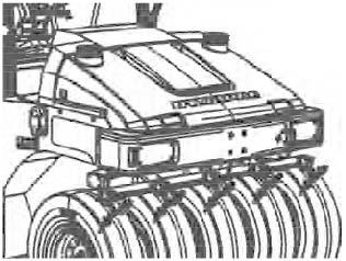
Diesel engine – Check oil level
The dipstick is located under the engine hood. Take care not to touch any hot parts of the engine or radiator when removing the dipstick. Risk of burns.
The dipstick is located down on the left side of the engine.
- Pull out the dipstick (1);
- Wipe the dipstick (1);
- Put the dipstick (1) in engine compartment;
- Pull the dipstick (1) out again, and then check the oil level through it.
For further details, refer to the engine’s instruction manual.
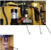
Hydraulic reservoir - Check fluid level
The filler pipe and sight glass are on the left side of the fan cover in the engine compartment.
Place the roller on a level surface and check that the oil level is between the max and min markings. Top up with the type of hydraulic fluid specified in the lubricant specification, if the level is too low.
Coolant level – Check
The expansion tank is placed in the middle, between the operator platform and the engine compartment. Refilling takes place from over the black cover between the operator platform and the hood.
To access the expansion tank you have to remove the protective plate (3) via two bolts (4).
Check that the coolant level is between the max. and min. marks (2).
Observe great caution if the cap has to be opened while the engine is hot. Wear protective gloves and goggles.
Fill with a mixture of 50% water and 50% anti freeze. See the lubrication specification in these instructions and the engine manual.
Flush the system every year and change the coolant. Also check that the air has unobstructed passage through the reservoir.
For further details, refer to the engine’s instruction manual.
Fuel tank – Refueling
Never refuel while the engine is running. Do not smoke and avoid spilling fuel.
The filler pipe and tank cap are behind the operator platform on the left side of the frame.
Refuel the tank every day before starting work, or fill the tank at end of work. Unscrew the lockable tank cap (1) and fill fuel up to the lower edge of the filler pipe.
The tank holds 320 liters of fuel. Refer to the engine manual for information on diesel grade.
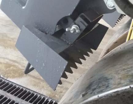
Wheel scrapers Control
Check that the tires and scrapers are worn evenly.
If there is uneven wear on the scraper, release the adjusting screw (3) on the back of the scraper attachment.
Pull down the scraper blade (1) so that it is flush with the tire.
Tighten the screws (3) again after adjusting.
The scrapers must hang free from the tires during transportation.
Lift up the scraper blades (1) and make sure that they are locked in raised position by the locking hooks (2).
To lower down the scrapers, lift the scraper slightly while pressing in the locking hook.
Removing the scrapers
The scrapers can easily be removed for cleaning and inspection.
First secure the scraper in the locking hook (3), placed on the scraper attachment (4), to prevent the scraper dropping onto the ground.
Release the pin (1) on the hook-up axle by removing the hairpins (2) on each side of the pin. Grip the up-hook axle and pull it straight out.
When refitting after inspection etc., the scraper must first be hooked in the locking hook before the hook-up axle is put in position.
Refit the pin (1) and make sure that it is well secured by the hairpins (2).
Water tank, Std – Filling
There are two filler caps on the top of the tank.
Unscrew the tank cap (1) and fill with clean water. Do not remover the strainer.
Fill the water tank; it holds 600 liters.
Only additive: A small amount of environment-friendly antifreeze.
Sprinkler system – Check
Fill the tank with emulsion fluid, e.g. water mixed with 2% cutting fluid. Check that the sprinkler nozzles (2) are not blocked, and if necessary clean them and the filter. See under Sprinkler system, Check – Cleaning, for detailed instructions.
Inspect the tire treads from time to time to ensure that no asphalt has stuck to the tires. This can happen before the tires have warmed up.
Fluids that are flammable or detrimental to the environment must not be used in the emulsion tank.
Sprinkler system
Cleaning of sprinkler nozzle
Dismantle the blocked nozzle by hand.
Blow the nozzle and fine filter (1) clean using compressed air. Alternatively, fit replacement parts and clean the blocked parts later on.
After inspecting and carrying out any necessary cleaning, start the system and check that it works.
Unscrew the tank cap (1) and fill with clean water. Do not remover the strainer.
Fill the water tank; it holds 600 liters.
Wear protective goggles when working with compressed air.
Sprinkler system – Freeze risk
Preventive measures when there is a risk of freezing.
Draining the system
- Close the valve (1).
- Separate the hose (2).
- Open the coarse filter (3).
- Loosen the intake to the pump by moving the plastic clamp to the left and pulling the white plastic adapter from the pump housing.
- Open the valves in the ends (4) of the sprinkler pipes.
- Allow the fluid to run out and run the sprinkler pump for about 10 seconds.
Freeze protection
Freeze protection can also be achieved by connecting a separate container, after dividing the hose, with water mixed with glycol and running approx. 2 liters in the system.
Brake fluid level – Check
Check every day that the fluid level is between the max/min marks.
Open the containers, which positioned on both front and rear of the frame.
Top up with brake fluid to the max mark on the container if the level is below the min mark.
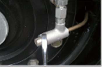
Tires – Tire pressure
Check the tire pressure with a pressure gauge.
Make sure that the tires have the same pressure.
Recommended pressure: See Technical Specifications.
The
Check
Wipe clean on both sides of the outlet pipe
Maintenance – 50h
Park the roller on a level surface. When checking and making adjustments to the roller, switch the engine off and make sure the Forward/Reverse lever is in the Neutral position.
Ensure that there is good ventilation (air extraction) if the engine is run indoors. Risk of carbon monoxide poisoning.
Air cleaner - Cleaning
Wipe clean the inside of the cover (2) and the filter housing (5). See the previous illustration.
Wipe also both surfaces for the outlet pipe; see adjacent figure.
Check that the hose clamps between the filter housing and the suction hose are tight and that the hoses are intact. Inspect the entire hose system, all the way to the engine.
Hydraulic fluid cooler - CheckingCleaning
The water and hydraulic fluid coolers are accessible when the cooler grill is removed.
Make sure that the air flow through the cooler is unobstructed. Dirty coolers are blown clean with compressed air or washed clean using a high-pressure water cleaner.
Take care when using a high-pressure water jet. Do not hold the nozzle too near the cooler.
Wear protective goggles when working with compressed air or high-pressure water jets.
Fuel filter – Draining
Unscrew the drain plug (1) at the bottom of the fuel filter.
With the aid of the secondary hand-operated pump, make certain that all sediment comes out. See Cummins service manual.
Tighten the drain plug as soon as uncontaminated fuel runs out.
Place in a suitable container and hand in to environment-friendly waste disposal station.
The air tank could also contain water due to condensation.
The condensation water removes by the drain valve (1), which resets automatically when loosening drain valve.
If a lot of water is drained, the system must be inspected and faulty parts should be replaced.
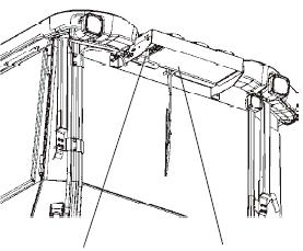
Air conditioning (Optional) – Drying filter – Inspection
Park the roller on a level surface, chock the wheels and the set the Forward/Reverse lever in the Neutral position.
With the unit in operation, check using the sight glass (1) that bubbles are not visible on the drying filter.
Make sure the Forward/Reverse lever is always in the Neutral position.
The filter is located on the top of the rear part of the cab roof. If bubbles are visible through the sight glass, this is a sign that the refrigerant level is too low. Stop the unit to avoid risking damage. Fill up with refrigerant.
Air conditioning (Optional) – Cleaning
If there is a significant loss of cooling capacity, clean the condenser element (1) on the rear edge of the cab roof.
Air conditioning (Optional) – Overhaul
Regular inspection and maintenance is necessary to ensure satisfactory long-term operation.
Clean all dust from the condenser element (1) using compressed air. Blow from above downwards.
The air jet can damage the element flanges if it is too powerful.
Wear protective goggles when working with compressed air.
Inspect the condenser element attachment.
Check the system hoses for chafing. Making sure that drainage from the cooling unit is unobstructed so that condensation does not accumulate inside the unit.
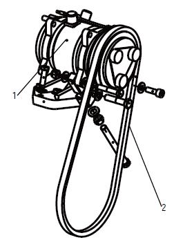
Air conditioner compressor belt - Check
Check the condition of compressor belt. Retighten if necessary.
Upper/Lower Pivot bearing –Lubrication
Lubricate nipple (1) on upper pivot bearing and nipples (2) on lower pivot bearing with five pump stokes from hand-operated grease gun.
Use grease as specified in the lubricant specification.
Draining of air reservoir
When the machine works in humid environment, the air reservoirs (2) need to drain every day.
Press the drainage valve (3) upwards until there is no water in the air reservoirs (2).
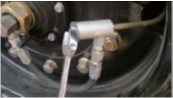
Tires – Tire pressure
Check the tire pressure with a pressure gauge. Make sure that the tires have the same pressure.
Recommended pressure: See Technical Specifications. The figure shows the position of the air valve on the outer tires.
The figure shows the position of the air valve on the inner tires.
Check the Safety Manual that accompanies the roller before filling the tires with air.
Maintenance – 250h
Park the roller on a level surface. When checking and making adjustments to the roller, switch the engine off and make sure the Forward/Reverse lever is in the Neutral position.
Ensure that there is good ventilation (air extraction) if the engine is run indoors. Risk of carbon monoxide poisoning.
Fuel filter – Replacing
Replace the fuel filter every 250 hours operation .
Place in a suitable container and hand in to environment-friendly waste disposal station.
Diesel engine – Oil change
The engine's oil drain plug is delivered under the rotatory support on the front of the frame through the rubber tube.
Unscrew the drain plug the engine oil could be changed.
Drain the oil when the engine is warm. Place a receptacle that holds at least 10 liters (11 qts) under the drain plugs.
Take great care when draining engine oil. Wear protective gloves and goggles.
Release the oil drain plug, and open the filler cap, allow all the oil to run out into a container.
Retighten the drain plug as soon as the engine oil runs out.
Deliver the drain oil for environmentally correct handling.
Fill with fresh engine oil; see Lubricant specification or the engine manual for the correct grade of oil.
Fill with the requisite volume of engine oil. See technical specifications before starting the machine.
Fuel filter is located on the left side in the engine compartment.
Unscrew the old one with special spanner, and then replace with the new one.
Start the engine and check that the filter is well sealed.
The oil filter (1) is located on the right side in the engine compartment.
See the engine manual for information about replacing the filter.
Oil – water separator – Draining
Unscrew the drain plug (1) at the bottom of the oil-water separator.
Tighten the drain plug as soon as uncontaminated fuel runs out.
Place in a suitable container and hand in to environment-friendly waste disposal station.
Oil – water separator – Replace
The oil-water separator is located at left side in the engine compartment.
Unscrew the old one with special spanner, and then replace the new one.
With help of hand pump, evacuate air in the filter.
Battery – Check condition
The batteries are sealed and maintenance-free.
Make sure there is no open flame in the vicinity when checking the electrolyte level. Explosive gas in formed when the alternator charges the battery.
When disconnecting the battery, always disconnect the negative cable first. When connecting the battery, always connect the positive cable first.
The cable shoes should be clean and tightened. Corroded cable shoes should be cleaned and greased with acid-proof Vaseline.
Wipe the top of the battery.
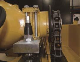
Driven chain maintenance
Normally, when the machine has worked over 250 hours, the driven chain needs maintaining
Loosen the bolts (1) and remove the cover (2), use the oilcan to instill gear oil on the driven chain (3); When the machine moves forward one third circle of the wheel, stop and instill again.
Repeat above steps until the whole driven chain (3) has been lubricated completely.
Repeat the procedure on the other side.
Don’t keep too much residual oil in the bottom of the chain box.
Water draining from chain bottom cover:
- Unscrew the plug (4) under each chain to drain water after heavy rain if the machine is kept outdoors and exposed in the opening space.
- Unscrew the plug (4) every month / every 250 working hours to drain the water.
- After draining the water each time, need to brush the correct and proper volume oil to lubricate the drive chain.
Also if there is too much water in the bottom cover, for sake of time saving, you have an option to remove the cover to drain water then reassemble.
Driving gear – Check oil level
Move the machine so that the level plug (3) is in horizontal position.
Wipe clean the area around the level plug (3) and then undo the plug.
Ensure that the oil level reaches up to the lower edge of the plug hole.
Replenish the oil to the right level if the level is low. Use transmission oil, see lubricant specifications.
Clean and refit the plugs.
Maintenance – 500h
Park the roller on a level surface. When checking and making adjustments to the roller, switch the engine off and make sure the Forward/Reverse lever is in the Neutral position.
Ensure that there is good ventilation (air extraction) if the engine is run indoors. Risk of carbon monoxide poisoning.
Hydraulic reservoir – Check
Unscrew and make sure that the reservoir cap is not clogged. Air must have unobstructed passage through the cap in both directions.
If passage in either direction is blocked, clean the filter with a little diesel oil and blow through with compressed air until the block is removed, or replace the cap with a new one.
Wear protective goggles when working with compressed air or high-pressure water jets.
Maintenance – 1000h
Park the roller on a level surface. When checking and making adjustments to the roller, switch the engine off and make sure the Forward/Reverse lever is in the Neutral position.
Ensure that there is good ventilation (air extraction) if the engine is run indoors. Risk of carbon monoxide poisoning.
Air cleaner
Checking – Change the main air filter
Change the air cleaner main filter when the warning lamp on the control panel comes on when the engine is running at maximum speed.
Release the clips (1), pull off the cover (2), and pull out the main filter (3).
Do not remove the backup filter (4).
Clean the air cleaner if necessary, see section Air cleaner – Cleaning.
When replacing the main filter (3) insert a new filter and refit the air cleaner in the reverse order.
Check the condition of the dust valve (6); replace if necessary.
When refitting the cover, make sure that the dust valve is positioned downwards.
Hydraulic filter Change
The hydraulic filters are located on the left side in the engine compartment, behind the battery disconnector.
Remove the filter and hand in to waste disposal station. This is a disposable filter and cannot be cleaned.
Thoroughly clean the filter holder sealing surface.
Apply a thin coat of fresh hydraulic fluid to the rubber gasket on the new filter.
Screw the filter on by hand, firstly until the filter gasket makes contact with the filter base. Then rotate a further ½ turn.
Check the hydraulic fluid level in the sight glass (1) and top off as required. See under the heading 'Every 10 hours of operation' for more information.
Start the engine and check that the filter does not leak.
Cab
Fresh air filter - Replacing
There is one fresh air filter (1), placed on the front of the cab.
Remove the protective cover.
Undo the screws (2) and remove the complete holder. Remove the filter insert and replace with a new filter.
The filter may need to be changed more often if the machine is operated in a dusty environment.
Wheel gear – Oil change
Take great care when draining the fluid. Wear protective gloves and goggles.
Note: When filling and draining the gear oil and checking the level of gear oil, always park the roller on a level surface.
Place a receptacle that holds at least 20 liters (5.3 gal) under the drain plug.
Unscrew the drain plug (1) and filler plug (2) to evacuate air. Allow all the oil to drain out and refit the plug.
Deliver the drain oil to environmentally correct handling.
Driving gear - Replenishing the oil
Move the machine so that the filler hole is correctly positioned. The hole should be just over the horizontal position to simplify filling.
Unscrew the filler plug (2). Unscrew the level plug (3) as well to evacuate air. Oil is filled from the filler well.
Fill up with approx. 20 l (21 qts) of new oil. Use transmission oil, see lubricant specifications.
Move the machine so that the level plug (3) is in horizontal position.
Ensure that the oil level reaches up to the lower edge of the plug hole.
Clean and refit the plugs.
Propulsion pump filter – Replace
Check the propulsion pump filter, replace of necessary.
Maintenance – 2000h
Park the roller on a level surface. When checking and making adjustments to the roller, switch the engine off and make sure the Forward/Reverse lever is in the Neutral position.
Ensure that there is good ventilation (air extraction) if the engine is run indoors. Risk of carbon monoxide poisoning.
Engine – Replace the coolant
The drain plug for the coolant is located at the back on the right side of the machine. The drain plug can be accessed by opening the panel in front of the exhaust pipe.

Drain the coolant when the engine is warm. Place a container that holds at least 14 liters (15qts) under the drain plugs.
Observe caution when draining the coolant. Wear protective gloves and goggles.
Release the hex nut (1) as shown (2).
Pull out the hose (3) and release the drain plug (4) for the coolant. Allow all the coolant to run out into a container.
To refit, secure the plug (4) as shown and push in the hose.
Secure as shown and then tighten the hex nut (1).
Hand in the drained coolant to an environment-friendly waste disposal station.
Hydraulic reservoir - Fluid change
Take great care when draining the hydraulic fluid. Wear protective gloves and goggles.
Hydraulic reservoir’s drain plug is located on the left front side of the frame, under the hydraulic reservoir. Open the drain plug to run out oil inside the hydraulic reservoir.
Place a receptacle that holds at least 80 liters (21 gal) under the engine compartment. Remove the plug on the end of the hose. Allow all the oil to run out. Reset by refitting the drain plug.
Deliver the drain oil to environmentally correct handling. Fill with fresh hydraulic fluid. Refer to the lubricants specification for grade information.
Replace the hydraulic filter. See section "Maintenance – 1000 hours”.
Start the engine and operate the hydraulic functions. Check the level in the reservoir and top off as required.
Water tank - Cleaning
Clean the tank with water and a suitable detergent for plastic surfaces.
Close the drain cock (1), fill with water and check for leaks.
The water tank is made of plastic (polyethylene) and can be recycled.
Cab – Fresh air filter – Replacing
There is one fresh air filter (1), placed on the front of the cab.
Remove the protective cover.
Undo the screws (2) and remove the complete holder. Remove the filter insert and replace with a new filter.
The filter may need to be changed more often if the machine is operated in a dusty environment.
Hydraulic oil change (2000 hours or 1 year)
1. Open the air filter cap (1), drain the oil.
2. Add hydraulic oil (Hydraulic 300) to about 2/3 place of the level gauge (1).
3. Retighten the air filter cap (1).
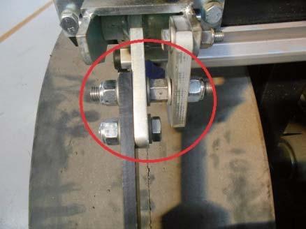
Drive chain - Adjustment
When the machine working over 2000 hours, it needs to adjust the drive chain so that the rear wheels can rotate freely.
Loosen the lock nuts (2) on the adjusting bolt (1). Turn the adjusting bolt (1) while rotating the wheel until the increase in tension slows the wheel down.
Check the distance: When pressing drive chain (3) by hand, it has 10 mm movement distance to obtain the right chain tension.
Tighten the lock nuts on the adjusting bolt (1).
Repeat the procedure on the other side.
Oil spray system
Before starting
Check the oil level of the tank, if the oil level warning LED is on please fill the “plant oil”
Check the distance between the cover and tire’s surface (1) no less than 20 mm.
Check the distance between the oil spray nozzle and tire’s surface is about 150mm;
The distance can be adjusted easily by through the fixing bolts (2) of the bracket to avoid over spraying beyond tire or missing spray.
CAUTION: The system must keep clean, use relatively high solidifying plant oil, such as soybean oil. In cold season, check oil by place the oil outdoor at night; if oil has been frozen, stop using the oil. Make sure only use unfrozen oil.
Starting
Switch on the battery switch; Ignition switch on, if the oil level is less than the low limit, the LED is on; Water/oil select switch turns to oil spray; Oil sprinkle time control. The position switch has 0~3 four positions. It means spray lasting 3s.6s.9s.12s.depends on which position is pre-selected; Press the oil spray switch.
Ev
Check the nozzles
Ev
Spray volume – Adjustment
Oil spray volume can be adjusted through the valve (1).
- Tighten to increase the volume;
- Unscrew to decrease the volume.
Since the oil viscosity has a big changing with temperature, If the viscosity change, should adjust the valve to keep the suitable volume.
Maintenance – Oil spray system (Optional)

If nozzle block, clean the nozzle; replace if necessary; If one of nozzles is blocked during working, the oil spray volume is on a normal level, clean the blocked nozzle during work break.
Clean the filters Remove the filters, clean the filters using plant oil cleanser; assemble the filter after the filter drying
Ev
Clean the oil tank
Remove the cover, clean the tank using plant oil cleanser, then wash the tank using normal plant oil. Drain the water of the oil tank.
Temporary cleaning
Clean the system after a long-term parking. Clean the system when any place block in working, if necessary, change the filter or pipe. Check the block place through the transparent pipe.
Long-term parking
Empty the system before long-term parking
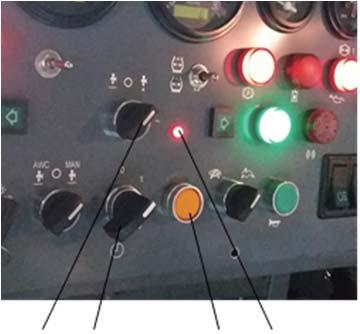
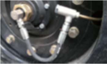
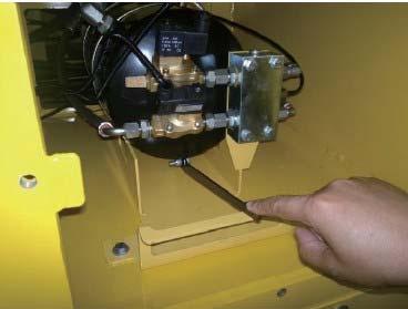
Air on the run (Optional) Before starting
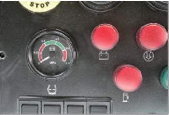
Check the air pressure from the air gauge on instrument panel, it should be in 380kPa – 780kPa. (fig1).
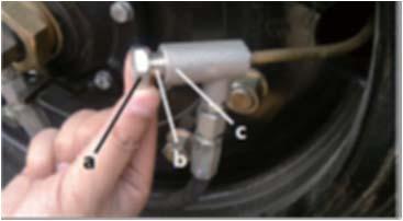
Check the air valve status:
In general, the air valves are closed when the roller is shipped out from factory. So if use the air on the run system, open the gas valve first on each tires. Fig 2, Fig 3
How to open / close the air valve Open the air valve
- Loosen the lock nut of the air valve using a wrench; Fig 4
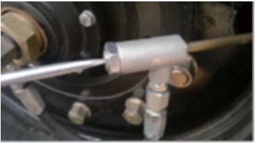
- Loosen the lock nut of the air valve using a flat screw driver; Fig 5
- Tighten the lock nut. Fig 6.
Close the gas valve.
Loosen the lock nut of the air valve using a wrench, screw out the valve element about 10mm with a screw driver, and tighten the lock nut.
Air charge and discharge
Air charge or discharge is control by the toggle switch on instrument panel; Push up is air charging and push down is air discharging, The neutral position is off.
Before operating the system, make sure the air pressure is normal and all the air valves are opened. Usually keep the nine tire’s pressure as the same about 600kPa, it will get the better compaction performance.
Maintenance - Air on the run (Optional)
Every day / 10 hours
Check the air pressure from the air gauge on instrument panel, it should be in 380kPa~780kPa.
Every week / 50 hours
Water drain of air tank; Fig 9.
Caution: In the case of the temperature is low, the water drain valve may be damaged by the water iced! Please drain the water more often.
Every 3 months / 250 hours
Check the air pipes of the system; Check the air valve.
Long-term parking
When long-term parking (more than one week), please to close the air valve, avoid leaking and damaging the tires!.
Disposal
Correctly sorted disposal must be carried out after replacing wear and spare parts and after the machine has been withdraw from service (scrapped).
The materials must be sorted correctly according to metal, plastic, electronic scrap, various operating substances etc.
Any oil greasy parts (hydraulic hoses, lube pipes etc.) must be treated separated.
Electric devices, accessories and packaging should be recycled in an environment–friendly manner.
Always observe the local regulations.
Air conditioning operation and maintenance (Optional)
1. Operation
Refrigeration: After starting the engine, turn on the COOL switch. For best results, run for one minute and then switch the temperature-control to the COOL position. At this time, the air conditioning system begins to work and the cab temperature begins to drop. When reaching the desired temperature, rotate the temperature-control switch counterclockwise until the compressor stops working. This will establish the desired indoor temperature. When the cab temperature is higher than the desired temperature, the indicator lamp is bright and refrigeration will automatically resume. When cab temperature is lower than the desired temperature, the indicator lamp goes off and the system stops working.
The fan control switch has three different speeds:high,medium and low. Cabin vents can be adjusted both vertically and horizontally to control the direction of air flow.
Notice: Please do not fasten the temperature-control switch to low-grade air vent to COOL position while using air condition, in case that the evaporator forms frost, influence the refrigeration result.
Cold warm air conditioner: please don’t turn on the hot water valve at the time of refrigeration in summer.
Heat: To operate the heater in the winter, close the temperature-control switch first. After the engine is started, open the switch and choose the HOT position. The hot water valve is opened at this moment. The air vent is opened and the indoor temperature begins to rise. When the desired temperature is reached, the air vent closes. When the temperature is lower than desired, the air vent will open again. The fan control switch has three different speeds:high,medium and low。 Cabin vents can be adjusted both vertically and horizontally to control the direction of air flow.
Notice:The heat source of the heating system adopts the engine cooling water, communicate with water tank of the engine, when the environment temperature is lower than 0 degree centigrade and the engine does not work, should put the water tank of the engine emptily, or annotate the anti-icing fluid in the water tank, so as not to freeze the heating system to crack and heat the core body.
2. Maintenance
In unsuited season for air conditioning function, need to keep A/C function running for 2-3 hours/month.
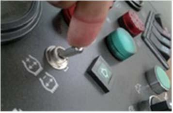
1. Display Parameters

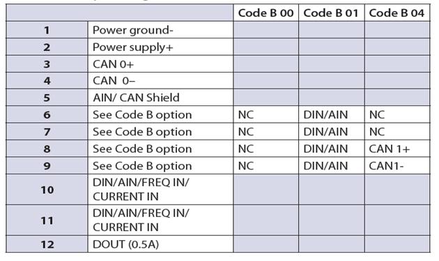
2. Pin assignments
Use care when wiring mating connector. Diagram shows device pins.