8 minute read
Machine description

from Dynapac Rubber wheel roller CP275 (IIIA/T3) Operating & Maintenance Manual 4812273203 - PDF DOWNLOAD

4700904165
Warning - Toxic gas
Read the instruction manual.
4700397286
Warning - High pressure fluid
Make sure to drain the pressure in the accumulators before opening the hydraulic system.
2017-08-25
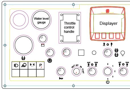
Locations - Control panel and controls
Location & control, cab

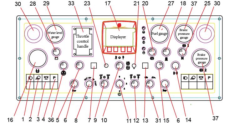
Function description of instruments and controls in the cab
No Designation Symbol Function
1 Heater control
2 Ventilation fan, switch
Turn to the right to increase heating. Turn to the left to reduce heating.
In the left position, the fan is off. Turning the knob to the right increases the volume of air entering the cab.
3 Air conditioning, switch Starts and stops the air conditioning.
Pressing the top opens the air damper so that fresh air comes into the cab.
4 Cab air recirculation, switch
Pressing the bottom closes the damper so that the air recirculates inside the cab.
5 Front wiper, switch Press to operate the front screen wiper.
6 Front and rear window screen washers, switch
Press the upper edge to activate the front screen washers. Press the lower edge to activate the rear screen washers.
7 Rear wiper, switch Press to operate the rear screen wiper.
8 Fuse box Contains fuses for the electrical system in the cab.
14 Defroster nozzle Turn the nozzle to direct the flow of air.
15 Hammer for emergency exit
To escape from the cab in an emergency, release the hammer and break the opening windows on the right-hand side.
2017-08-25
Using the cab controls
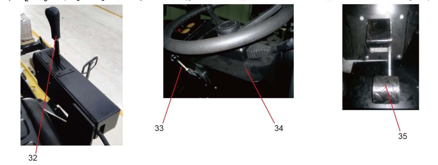
Defroster
To quickly remove ice or mist, make sure that only the front and rear air nozzles are open. Turn the heater and fan dial (1 and 2) to max. Adjust the nozzle so that it blows on the window to be be-iced, or to remove mist.
Heat
If the cab is cold, open the lower nozzle on the front columns and the middle nozzles just over the controls for the heater and fan. Turn to max heat and max fan speed. When the required temperature has been reached, open the other nozzles and if necessary turn down the heat and fan speed.
Ac
NOTE: When using AC all the windows must be closed for the system to work efficiently.
To quickly reduce the temperature in the cab, adjust the following settings on the control panel. Turn on AC (3) and set the fresh air (4) in the lower position to switch off the fresh air valve. Set the heater control (1) to minimum and turn up the fan speed (2). Keep only the front middle nozzles in the ceiling open.
When the temperature has dropped to a comfortable level, adjust the required temperature on the heater control (1) and reduce the fan speed (2).
Now open the remaining nozzles in the roof to achieve a comfortable temperature in the cab. Reset the fresh air button (4) to the upper position for fresh air.
Electrical system
The machine's main switchbox (fig1.) is located on the rear of the operator platform. There is a plastic cover over the switchbox and fuses.
On the plastic cover there is a 24V socket.
The roller is equipped with 24 V electrical system and an AC alternator.
Connect the correct polarities (ground) to the battery. The cable between the battery and the alternator must not be disconnected when the engine is running.
Machine description
Fuse
The figure shows the position of the fuses. The table in below gives fuse amperage and function.
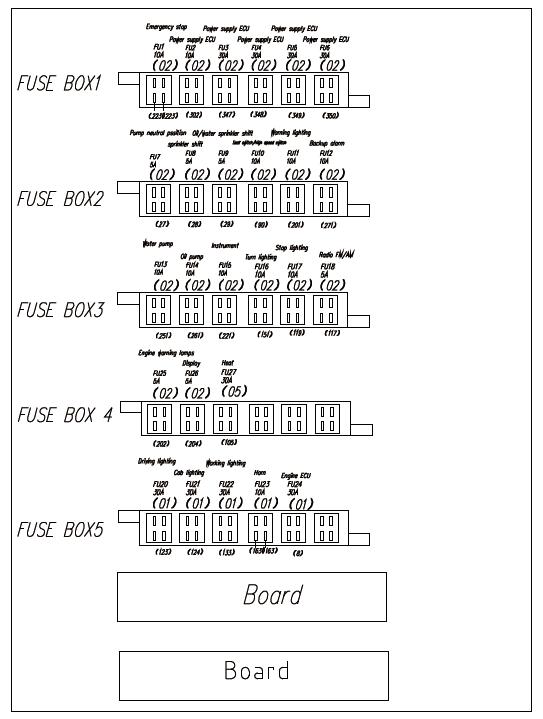
FUSE BOX1
F1: 10A Emergency stop
F2: 10A Power supply ECU
F3: 30A Power supply ECU
F4: 30A Power supply ECU
F5: 30A Power supply ECU
F6: 30A Power supply ECU
FUSE BOX3
F13: 10A Water pump
F14: 10A Oil pump
F15: 10A Instrument
F16: 10A Turn lighting
F17: 10A Stop lighting
F18: 5A Radio FM/AM
FUSE BOX5
F20: 30A Driving light
F21: 30A Cab lighting
F22: 30A Working lighting
F23: 10A Horn
F24: 30A Engine ECU
Cab fuse
FUSE BOX2
F7: 5A Pump neutral position
F8: 5A Sprinkler shift
F9: 5A Oil/water sprinkler shift
F10: 10A Seat switch/High speed switch
F11: 10A Warning lighting
F12: 10A Backup alarm
FUSE BOX4
F25: 5A Engine warning lamps
F26: 5A Display
F27: 30A Heat
The figure shows the position of the fuses. The table in below gives fuses function. All fuses are flat pin fuses. amperage and
Driver seat - Adjustment
Operation
Before starting Master switch – Switching on Remember to carry out daily maintenance. Refer to the maintenance instructions.
The battery disconnector is located in the engine compartment, on the right side of engine parts. Open the engine hood, turn the key (1) to the On position. The roller is now supplied with power.
If the main battery/master switch is covered, the engine hood must be unlocked driving operation, to be able to reach the switch in an emergency.
Do not run the starter motor for too long(max. 30 seconds). If the engine will not start, wait two minutes before trying again.
Adjust the operator’s seat so that the position is comfortable and so that the controls are within easy reach.
The seat can be adjusted as follows.
- Length adjustment (1).
- Back support angle (2).
Always make sure that the seat is secure before beginning operation.
Before starting
1. Control panel and lights - Check
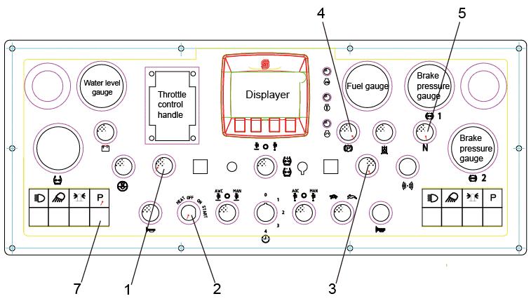
Turn the ignition key (2) to “ON” position, neutral position indicator (5), parking indicator (4) and control indicator (1) or (3) on operator side are all activated. Make sure the parking brake button (7) is on “pressed” condition. Make sure the emergency stop button is on “unpressed” condition. Make sure the fuel gauge, water level gauge have readings, oil pressure alarm is “on”.
To start the machine the forward/backward lever must be in neutral position, in the middle.
3. Parking brake - Check Parking brake – Check
Check tire pressure for all tires ensure the pressure accuracy.
Check the “tire pressure gauge” (2) (option) on the control panel, move the manual pressure control valve (1) in the middle, move it upward to increase pressure, downward to decrease pressure.
Or check each tire’s pressure by using tire pressure gauge.
Test the brake valve function; ensure the normalcy of this function is essential for normal operating the machine.
Test through pressing the brake pedal (3), the brake pressure indicator will be activated.
View
Before starting, make sure that the view ahead, to the rear, and to the sides is unobstructed.
All cab windows should be clean and the rear view mirrors should be correctly adjusted.
Operator position
If a ROPS (Roll Over Protective Structure) or a cab is fitted to the roller, always wear the seat belt provided and wear a protective helmet.
Replace the seat belt if it shows signs of wear or has been subjected to high levels of force.
If the machine is fitted with a cab, make sure that the door is closed when in motion.
Interlock
The roller is equipped with Interlock.
The diesel engine switches off after 7 seconds if the operator rises from the seat when going forwards/backwards.
If the Forward/Reverse lever is in neutral, when the operator stands up a buzzer will be activated until parking switch is activated.
The engine does not stop if the parking brake is activated.
The engine will switch off immediately if for any reason the Forward/Reverse lever is moved out of neutral when the operator is not sitting down in the seat.
Sit down for all operations!
Operating the roller
Under no circumstances is the machine to be operated from the ground. The operator must be seated inside the machine during all operation.
Check that the steering is working correctly by turning the steering wheel once to the right and once to the left while the roller is stationary.
When compacting asphalt, remember to turn on the sprinkler system.
Make sure that the area in front of and behind the roller is clear.
In below there are some speed recommendation according to different working conditions: First gear speed (tortoise): Used for variety different material session Used for climbing working condition
Second gear speed (rabbit): Used for transportation
Speed selecting
While roller is stationary, change the direction or change gears.
When the tire temperature is low, from time to time to check tire surface to ensure whether asphalt mixture stuck to the tire, sprinkle water or oil on the tire could effectively prevent this problem.
Operating on a slope
Under no circumstances is the machine to be operated from the ground. The operator must be seated inside the machine during all operation.
When transporting on steep ground (downward slope > 5%) make sure not to exceed the maximum speed for the roller.
Selecting low speed increases the efficiency of the engine brake and prolongs the brake life.
Low speed should always be selected when working and transporting on steep slopes (>15%).
The driving and braking rear wheels should also always be pointing down the slope, i.e. the roller is driven forwards up the slope and reversed down the slope.
Make sure that the area in front of and behind the roller is clear.
Checking the treads on the tires
Inspect the tire treads from time to time to ensure no asphalt has stuck to the tires. This can occur before the tires are sufficiently warm. Mixing 2-4% cutting fluid to the tire sprinkler water can prevent this problem.
Variable tire pressure (air-on-the-run) (Option)
The operator can vary the pressure while work is in progress with the air pressure control on the roller.
The pressure is variably by adjusting the keys (fig1) on the keypad. Pressure adjusting interval is between maximum 780kPa (110psi) and minimum 380kPa (55psi). Push the key to upward position (1) to increase the pressure; push the key downward (2) to reduce the pressure.
The pressure level of the tire is shown on the pressure gauge on the top left corner of the instrument board.
The tire pressure should not be lower than 380 kPa, otherwise it would impair the service life of the tire.
Increase ballast from both side of the frame
Remove the top left cover (1), rear left cover (2), top right cover (3), and the rear right cover (4).
The machine can use 12 steel blocks of 6 types of steel blocks as ballast in the lower of the frame. Red type blocks are mounted on the front; black type blocks are mounted on the rear.
Use a suitable combination to achieve max ballast.
The roller’s service weight consists of the weight of the roller plus the weight of the ballast.
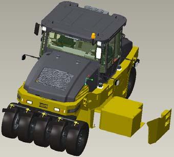
Fig. Ground contact surface
1. Contact surface at high tire pressure
2. Contact surface at low tire pressure
Driving (Ground Pressure)
Ground pressure
The contact surface of the tire can be changed by means of tire pressure.
High tire pressure gives a smaller contact surface (1).
Low tire pressure gives a larger contact surface (2).
The total service weight divided by the number of tires give the pressure per wheel. See Table.
The ground contact surface of the tire is relevant for the compaction result.
Low tire pressure – 380 kPa (55 psi)
The lower the tire pressure, the lower the pressure on the contact surface due to larger contact surface.
Is used on lots of loose material.
Normal tire pressure – 510 kPa (70 psi)
Used for degradation session.
High tire pressure – 780 kPa (110 psi)
The higher the tire pressure, the greater the pressure on the contact surface due to smaller contact surface.
Used for thick layers and finishing sessions.