3 minute read
I. Heating and Air Conditioning System


CLUTCH
GENERAL DESCRIPTION
The vehicle, when equipped with the five speed manual transmission, uses a single dry disc type clutch. The clutch is hydraulically operated. The pressure plate is adiaphram spring type and the disc has a spring cushioned hub. A self-aligning, sealed ball-type throw-out bearing is used to depress the diaphram spring. The clutch has its own fluid reservoir and master cylinder which provides hydraulic pressure when the clutch pedal is depressed.
OPERATION
The clutch pedal is connected to the master cylinder with a pushrod. When the pedal is depressed, the pushrod exerts pressure against the master cylinder piston. As the piston begins to move, it draws fluid from the fluid reservoir and forces it through the hydraulic line to the slave cylinder piston. Slave cylinder piston pressure causes the clutch fork to move the throw-out bearing against the pressure plate. As the diaphram spring is depressed, pressure on the disc is released and the clutch disengages. When the clutch pedal is released, the procedure is reversed and the clutch engages.
©<£D3J>(5a>»
TRANSMISSION - AUTOMATIC
GENERAL DESCRIPTION
The three (3) speed automatic transmission uses a conventional torque converter. This converter has a single stator supported on a one-way roller clutch. The final drive unit is contained within the transmission case. Gear reduction, direct drive, and reverse are achieved using one (1) planetary gear set, two (2) reaction members, and two (2) internal clutch packs. Hydraulic pressure for this transmission is developed with a crescent gear type oil pump. The pump is driven by a shaft which runs the entire length of the transmission case. This shaft is splined to the converter and turns at engine speed. Main line pressure is regulated by a pressure regulator valve and a vacuum operated actuator. As engine vacuum decreases, the valve increases main line pressure to assure positive application of the clutches and reaction members. The shift valves in the valve body are controlled by a computer governor assembly and two (2) electric solenoids. By comparison, a conventional valve body uses a mechanical governor and a vacuum modulator (or throttle valve) to perform this same function. The valve body is not servicable and must be replaced as a unit if required. The hydraulic transmission is operated and lubricated by automatic transmission fluid while the final drive assembly is in a separate area filled with gear lube.

FRONT SUSPENSION
GENERAL DESCRIPTION
The front suspension is a fully independent type with upper and lower control arms, stabilizer bar and steering knuckle assembly. Telescopic shock absorbers, secured to the chassis frame tower at the absorber's upper end and to the lower control arm at the absorber's lower end, are positioned through the coil springs. The single front hub bearing supports the hub assembly on the spindle which is fastened to the steering knuckle. The steering knuckle is secured to the upper and lower control arms with upper and lower ball joints and to the steering system with an adjustable ball-type tie rod.

REAR SUSPENSION
GENERAL DESCRIPTION
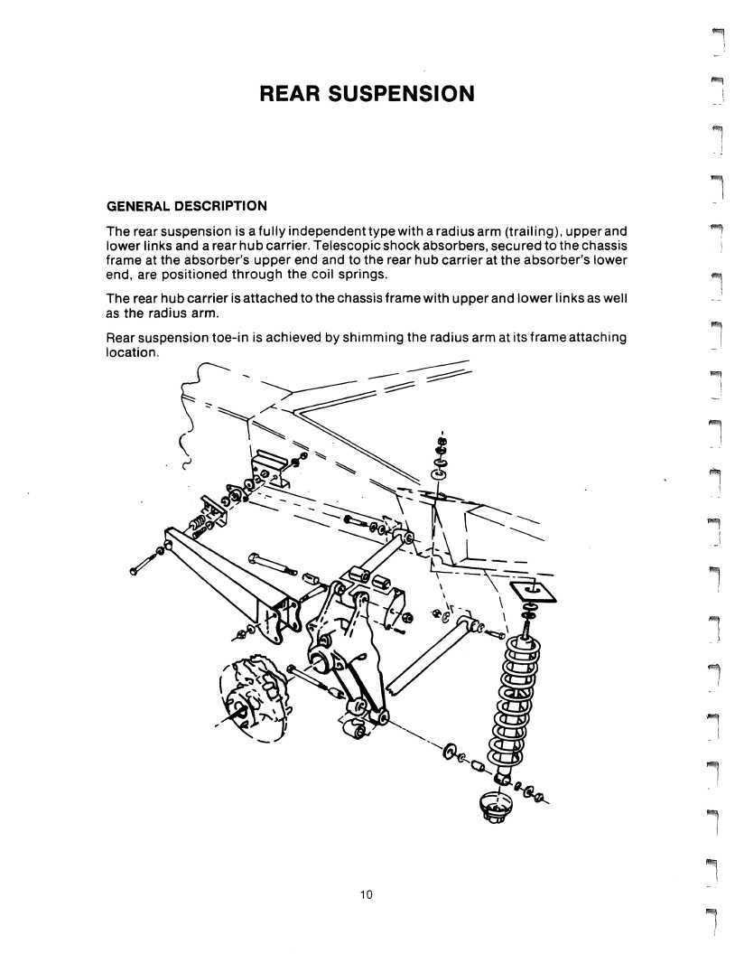
The rear suspension is afully independent type witharadius arm (trailing), upper and lower links and a rear hub carrier. Telescopic shock absorbers, secured to the chassis frame at the absorber's upper end and to the rear hub carrier at the absorber's lower end, are positioned through the coil springs. The rear hub carrier is attached to the chassis frame with upper and lower links as well as the radius arm.
Rear suspension toe-in is achieved by shimming the radius arm at its frame attaching location.