4 minute read
F. Door Operated Interior Lamp Circuits


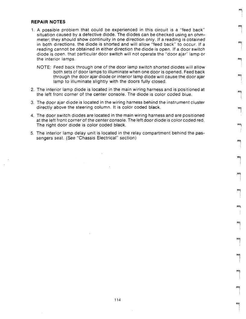
REPAIR NOTES
1. A possible problem that could be experienced in this circuit is a "feed back" situation caused by a defective diode. The diodes can be checked using an ohmmeter; they should show continuity in one direction only. If a reading is obtained in both directions, the diode is shorted and will allow "feed back" to occur. If a reading cannot be obtained in either direction the diode is open. If a door switch diode is open, that particular door switch will not operate the "door ajar" lamp or the interior lamps.
NOTE: Feed back through one of the door lamp switch shorted diodes will allow both sets of door lamps to illuminate when one door is opened. Feed back through the door ajar diode or interior lamp diode will cause the door ajar lamp to illuminate slightly with the doors fully closed. 2. The interior lamp diode is located in the main wiring harness and is positioned at the left front corner of the center console. The diode is color coded blue.
3. The door ajar diode is located in the wiring harness behind the instrument cluster directly above the steering column. It is color coded black. 4. The door switch diodes are located in the main wiring harness and are positioned at the left front corner of the center console. The left door diode is color coded red.
The right door diode is color coded black. 5. The interior lamp delay unit is located in the relay compartment behind the passengers seat. (See "Chassis Electrical" section)

ENGINE ADJUSTMENTS, TESTS AND DIAGNOSIS
ENGINE ADJUSTMENTS, TESTS AND DIAGNOSIS
A. Adjustment 1. Ignition Timing *. 2. Idle Speed ] 3. CO Emission B. System Operation Tests ^ 1. Lambda i 2. Idle Speed Control C. Diagnostic Charts H 1. "Engine will not start" — Ignition System 2. "Engine will not start" — Fuel System 3. Lambda System Troubleshooting m^ 4. Troubleshooting |


A1 — IGNITION TIMING ADJUSTMENT
STEP 1: Connect tachometer to engine. Start engine and allow to warm up to normal operating temperature. STEP 2: Check engine curb idle speed to see that it is within specification (775 RPM ± 50, auto trans, in park). If idle speed is not within specification, perform "Idle Speed Control System Operation Test", item B2 in this section. STEP 3: Disconnect vacuum hose at distributor advance and check to see there is not vacuum at the hose. Reconnect hose to advance unit. If vacuum is present at hose during idle speed, diagnose malfunction in idle speed control system, (i.e., limit switch adjustment, distributor vacuum cutoff solenoid, TVS switch). STEP 4: Connect timing light to #1 cylinder and check ignition timing. Set timing to 13° ±2 BTDC at curb idle (775 RPM + 50), adjust timing by loosening distributor hold-down nut and rotating distributor assembly. Stop engine. STEP 5: Tighten distributor hold-down nut and disconnect timing light.
A2 — IDLE SPEED ADJUSTMENT
The De Lorean is equipped with an electronic idle speed control system. This system continuously monitors engine idle RPM and electronically maintains afixed curb idle speed. Thecurb idlespeed is pre-determined within the factory installed ECU module and cannot be altered. The engine should idle at 775 RPM ±50 during normal engine operating temperature. This check is made with an external tachometer connected to the engine. If there is excessive deviation from specification, the "Idle Speed Control System Operation Test" (B2 in this section) should be performed.
A3 — CO EMISSION ADJUSTMENT
Since the De Lorean is equipped with an Idle Speed Control System, there is no provision to balance CO between left and right cylinder banks. This is due to the engine idle speed screw being completely closed and therefore non-functional. The only CO adjustment is total CO emission of left and right cylinder banks combined. This adjustment is performed with the air flow sensor adjusting screw.
ENGINE CO EMISSION CHECK:
STEP 1: Connect tachometer to engine. STEP 2: Disconnect Lambda oxygen sensor wire from under vehicle at underbody connection located above left rear suspension. Do not attempt removing wire directly from oxygen sensor. STEP 3: By-pass cooling fan temperature switch by disconnecting connectors from
switch and installing a jumper wire between the terminals in the connectors.
The temperature switch is located on the coolant pipe, left side of engine.
STEP 4: Remove both exhaust pipe plugs. Plugs are located in left and right exhaust pipes at exhaust manifolds. STEP 5: Install exhaust gas probes and valve assembly, Tool No. J28886, in plug
locations. Connect CO analyzer to probe and valve assembly. STEP 6: Start engine and allow to warm up to normal operating temperature.
STEP 7: With both left and right gas probe assembly valves in the open position, read CO level. It should be 1.0% + .3% at an engine speed of 950 RPM. If not, perform "Air Flow Sensor Adjustment" (Page 120). Note: To adjust idle speed to 950 RPM, open idle adjustment screw (slotted screw on inlet manifold).

Iv^S,
STEP 8: Reconnect cooling fan temperature switch and Lambda oxygen sensor wire. Remove exhaust gas probe an I wire. Remove exhaust gas probe and valve assembly, and install exhaust
pipe plugs. Disconnect tachometer.
STEP 9: Close idle adjustment screw.
119