2 minute read
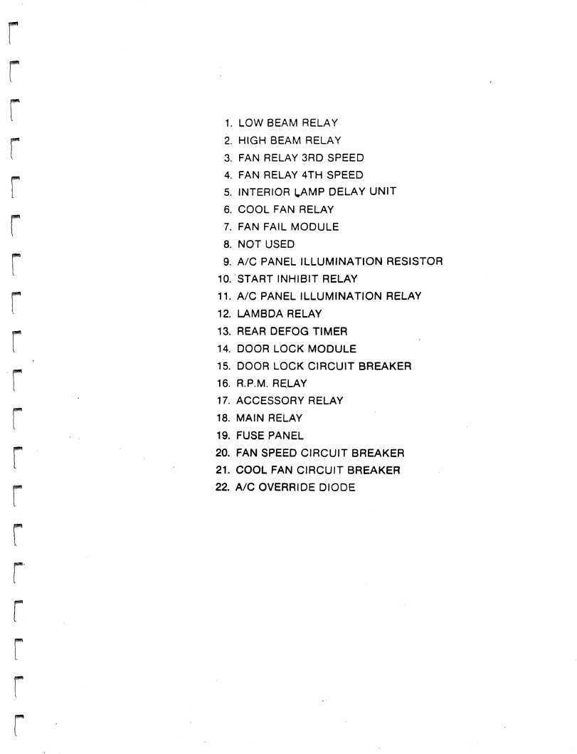
B. Relay Compartment


1. LOW BEAM RELAY 2. HIGH BEAM RELAY 3. FAN RELAY 3RD SPEED 4. FAN RELAY 4TH SPEED 5. INTERIOR LAMP DELAY UNIT 6. COOL FAN RELAY 7. FAN FAIL MODULE 8. NOT USED 9. A/C PANEL ILLUMINATION RESISTOR 10. START INHIBIT RELAY 11. A/C PANEL ILLUMINATION RELAY 12. LAMBDA RELAY 13. REAR DEFOG TIMER 14. DOOR LOCK MODULE 15. DOOR LOCK CIRCUIT BREAKER 16. R.P.M. RELAY 17. ACCESSORY RELAY 18. MAIN RELAY 19. FUSE PANEL 20. FAN SPEED CIRCUIT BREAKER 21. COOL FAN CIRCUIT BREAKER 22. A/C OVERRIDE DIODE
IGNITION SWITCH CIRCUITS
CIRCUIT DESCRIPTION
A three position ignition switch is used to control the operation of the starter motor, two relays, and the ignition key warning buzzer. The various positions of the ignition switch control the operation of the relays which in turn supply power to most fused circuits.
CIRCUIT OPERATION
The ignition switch receives power from the main feed wire which is "hot" at all times. Placing the switch in position 1 or "accessory position", allows current to flow from the ignition switch to the accessory relay thus activating the relay and closing the contact points. When this relay is activated, power is supplied to fused circuits 9, 10, 11, 13, and 16 from the main feed wire. Placing the ignition switch in position 2 or "run position", activates the main relay. This relay connects fused circuits 1, 3, 4, and 5 to the main feed wire. The accessory relay remains activated when the ignition switch is in position 2. By moving the switch to position 3 or "start position", power is supplied to the start inhibit relay which controls the operation of the starter motor. The accessory relay is deactivated during the cranking process and will reactivate when the spring loaded ignition switch is released and returns to the "run" position. The mam relay remains activated during cranking to supply power to the circuits that are required for the starting process. When the ignition key is inserted into the ignition switch, an electrical circuit is completed from the buzzer unit. This unit activates the buzzer if the driver's door is opened and the key is in the ignition switch.
REPAIR NOTES
1. The ignition switch can be removed from the lock cylinder/steering column lock assembly for replacement. It is not necessary to remove the lock assembly to perform this operation. 2. The relays are in the relay compartment located behind the passenger seat. (See "Chassis Electrical" section) 3. The ignition key buzzer module is located under the instrument panel on the left side of the steering column.