8 minute read
A. Electronic Ignition System


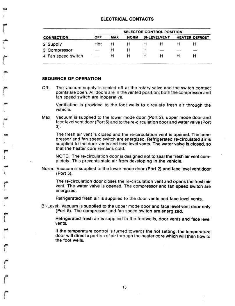
SELECTOR CONTROL POSITION CONNECTION OFF MAX NORM BI-LEVELVENT HEATER DEFROST
2 Supply Hot H H H H H H 3 Compressor — H H H — — — 4 Fan speed switch — H H H H H H
SEQUENCE OF OPERATION
Off: The vacuum supply is sealed off at the rotary valve and the switch contact points are open. All doors are in the vented position; both the compressor and ifan speed switch are inoperative. Ventilation is provided to the foot wells to circulate fresh air through the vehicle.
Max: Vacuum is supplied to the lower mode door (Port 2), upper mode door and face level vent door (Port 5) and to the re-circulation door and water valve (Port 3). The fresh air vent is closed and the re-circulation vent is opened. The compressor and fan speed switch are energized. Refrigerated re-circulated air is supplied to the door vents and face level vents. The water valve is closed, so that the heater core remains cold.
NOTE: The re-circulation door is designed not to seal the fresh air vent completely. This prevents stale air from developing in the vehicle. Norm: Vacuum is supplied to the lower mode door (Port 2) and face level vent door (Port 5). The re-circulation door closes the re-circulation vent and opens the fresh air vent. The water valve is opened. The compressor and fan speed switch are energized. P Refrigerated fresh air is supplied to the door vents and face level vents. Bi-Level: Vacuum is supplied to the upper mode door and face level vent door only (Port 5). The compressor and fan speed switch are energized. Refrigerated fresh air is supplied to the footwells, door vents and face level vents.
If the temperature control is turned towards the hot setting, the temperature door will direct a portion of air through the heater core which will then flow to the foot wells.
Vent: Vacuum is supplied to the lower mode door (Port 2) and to the upper mode door and face level vent door (Port 5). The compressor is off; the fan speed switch is energized. Ambient fresh air is supplied to the door vents and face level vents. Heater: The vacuum supply is not present and electrical current is supplied to the fan speed switch only. As the temperature control is turned towards the maximum hot setting, the temperature door directs an increasing portion of air through the heater core and then to the foot wells. The windshield vent door is designed not to seal completely, a certain amount of the hot air will be directed to the windshield vent, and to the bridging duct to the door vents, for defogging purposes. Defrost: Vacuum is supplied to the windshield vent door (Port 4). Electrical current is supplied to the fan speed switch only. With the temperature control turned to the maximum heat setting, air is directed through the heater core and is distributed to the windshield and door vents. A certain amount of hot air will be directed to the foot wells.
NOTES
The heater core water valve is open at all times except when the re-circulcition door is operated (maximum setting). Heated air is only available i* the temperature control directs air through the heater core. The selector switch may be removed for access to the vacuum harness or e\ectrica\ contacts.
REFRIGERANT CYCLE: The refrigerant cycle begins at the compressor where refrigerant enters as a low pressure, low temperature vapor. After being compressed, it leaves as a high pressure, high temperature vapor. This vapor flows to the condenser where it is cooled by air flow through the condenser. As the refrigerant vapor gives up heat, it changes from high pressure, high temperature vapor to high pressure liquid. The liquid then passes through the orifice tube where it becomes a low pressure, low temperature liquid. This liquid enters the evaporator core absorbing heat from the vehicles interior compartment. The absorbtion of heat causes the liquid to change to a low pressure, low temperature vapor. This vapor, and the small amount of low pressure liquid that did not vaporize completely, enters the accumulator where the liquid is separated and trapped until it also vaporizes. From the accumulator, the low pressure vapor returns to the compressor where the cycle begins again. A pressure relief valve is built into the system between the condenser and the orifice tube. This valve is placed in the system as a safety device. This valve is designed to open automatically at approximately 440 psi, thus venting the system to atmosphere and helps prevent any damage from occuring at excessive pressures. PRESSURE SENSING/CYCLING SWITCH: The pressure sensing switch is located near the top of the accumulator. Its function is to cycle the compressor off at 20 to 28 psi and back on at 41 to 51 psi to maintain cooling and prevent evaporator freeze-up. The pressure switch also turns the compressor off when accumulator pressure falls below approximately 23 psi. This function protects the compressor if system is undercharged or if ambient temperature is below 37°F.


BODY AND CHASSIS
GENERAL DESCRIPTION
The vehicle's body is made of structural composite glass reinforced plastic (GRP). The upper and lower halves are molded separately, then bonded together to form the body shell. Plastic is laid over pre-formed foam panels. The foam provides a larger surface to cover with plastic which gives more rigidity to the body shell. The body shell is covered with high quality grade 304 brushed stainless steel body panels to give the car its unique appearance. No paint or sealers are used on the exterior body and it is virtually corrosion-free. The chassis consists of an epoxy coated steel backbone (center tunnel) frame, with front and rear wishbones, supporting crossmembers and 4-wheel fully independent suspension. The front crossmember carries the steering and front suspension components. The rear crossmember is welded to the center backbone and carries the engine and transaxle assemblies. The bumpers, sills, and spoiler are semi-rigid endura polyurethane, capable of considerable flexing without breakage. The doors are counter-balanced gull wing type which use torsion bars for balancing and gas struts for holding them open. Other standard features of the car include: - Leather seating area - Air Conditioning r Electrically operated windows - Adjustable steering wheel (tilt & telescoping) - Electrically operated remote control side door mirrors - Central door locking system - Tinted glass

ENGINE ELECTRICAL
ELECTRONIC IGNITION SYSTEM
SYSTEM DESCRIPTION
The De Lorean is equipped with a Bosch electronic ignition system. This breakerless ignition system is similar to a conventional ignition system except for the following modifications.
The breaker points in the distributor have been replaced by a pulse generator consisiing of a stator, an induction coil and a trigger wheel. The pulse generator is connected to an electronic control unit (ECU) module in which the signal from the distributor is converted and amplified. The ECU module is connected to a high voltage ignition coil.

1 - Distributor
2 - ECU module 3 - Compensating resistor
4 - Coil
SYSTEM OPERATION
DISTRIBUTOR: The distributor containsapulsegeneratorwhich corresponds to the breaker points in a conventional distributor. The trigger wheel is attached to the distributor shaft and is designed with six fingers (poles). The stator, induction coil, and magnet are formed into one unit which is attached to the distributor plate. The stator is also designed with six fingers (poles). When the trigger wheel rotates, an alternating voltage is produced in the pulse generator. This pulse is transmitted to the ECU module and its voltage will vary between 0.3V and 100V depending on engine speed. The alternating voltage is produced by the trigger wheel passing through a magnetic field which creates a voltage in the induction coil. As the pole on the trigger wheel approaches the pole on the stator, a positive voltage is produced. The voltage then reverses polarity as the poles separate. The ECU module creates secondary ignition spark when the poles are directly aligned with each other.
1—Trigger Wheel 2—Stator 3—Induction Coil 4—Magnet

r i
o
N ' U "U [ vL
<D
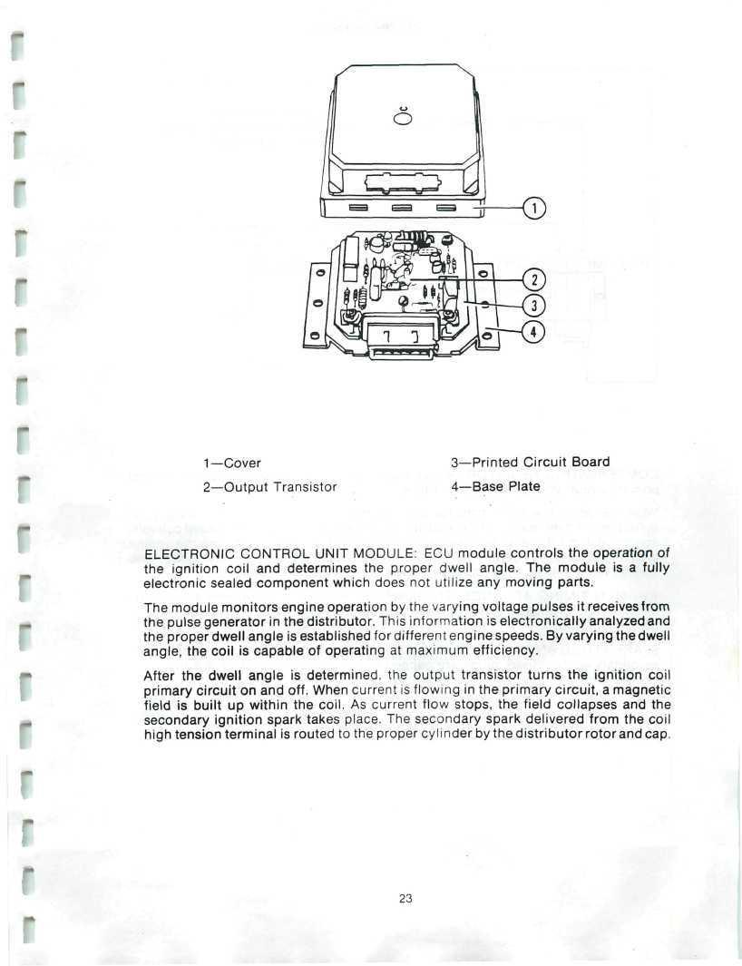
1—Cover 2—Output Transistor 3—Printed Circuit Board
4—Base Plate
ELECTRONIC CONTROL UNIT MODULE: ECU module controls the operation of the ignition coil and determines the proper dwell angle. The module is a fully electronic sealed component which does not utilize any moving parts. The module monitors engine operation by the varying voltage pulses it receives from the pulse generator in the distributor. This information is electronically analyzed and the proper dwell angle is established for different engine speeds. By varying the dwell angle, the coil is capable of operating at maximum efficiency. After the dwell angle is determined, the output transistor turns the ignition coil primary circuit on and off. When current is flowing in the primary circuit, a magnetic field is built up within the coil. As current flow stops, the field collapses and the secondary ignition spark takes place. The secondary spark delivered from the coil high tension terminal is routed to the proper cylinder by the distributor rotor and cap.
0.5 OHM hA 0.5 OHM
i i i i i '^
Compensating I I >PI I I I • i i P1 Resistor
O To ECU module COMPENSATING RESISTOR: A dual resistance ballast resistor is used to control primary circuit voltage and current flow. When the ignition switch is in the run position, the current flow is reduced by the resistor to prevent overheating of the coil during operation. To provide increased coil voltage for starting the engine, one-half of the resistor is bypassed during the engine cranking process. By reducing the circuit resistance, the coil primary voltage and current will increase, thus increasing the secondary output voltage. IGNITION TIMING ADVANCE: The Bosch distributor provides timing advance by means of a centrifugal advance unit and a vacuum advance unit the same as a conventional distributor. SPARK PLUGS AND WIRES: Bosch HR6DS spark plugs are used with copper core secondary wiring. Spark plugs are gapped to 0.6 - 0.7 mm (0.024 - 0.028 in).
From starter motor solenoid "Hot" during cranking only.
From main relay "Hot" when ignition switch in run or start position.
#15