3 minute read
D. Cooling Fan Circuit


SYSTEM REPAIR NOTES
1. The starter motor may be overhauled depending upon the extent of repair.
Solenoid, drive gear, brushes, linkage and armature bushings are available for replacement. 2. The start inhibit relay is located in the relay panel in the relay compartment behind the passenger seat. (See "Chassis Electrical" section) 3. The automatic transmission neutral start switch is part of the valve body controls and is not adjustable. 4. The electrical portion of the ignition switch can be replaced without removing the lock cylinder and steering lock assembly.
CHARGING SYSTEM
SYSTEM DESCRIPTION
The car is equipped with a Ducellier 80 amp alternator containing an integral voltage regulator. The alternator consists of a "delta" connected stator, a six diode rectifier bridge, and a "claw pole" rotor which is controlled by an electronic voltage regulator. When the ignition switch is turned to the "start" or "run" position, the main relay supplies power to the voltage regulator and the "charge" indicator lamp. The charge indicator lamp operation is controlled by the voltage regulator. Whenever the ignition switch is in the "run" position and the alternator is not producing voltage, the voltage regulator will allow current to flow through the indicator bulb circuit, lighting the lamp. Any voltage produced by the alternator, above that of the battery, will cause the voltage regulator to turn the indicator lamp off.
N — BROWN W — WHITE G — GREEN NY — BROWN/YELLOW
To Battery Pos. Terminal via
Starter Moter connection From Main Relay-"HOT" when ignition switch is in Run or Start position
CHARGING CIRCUIT

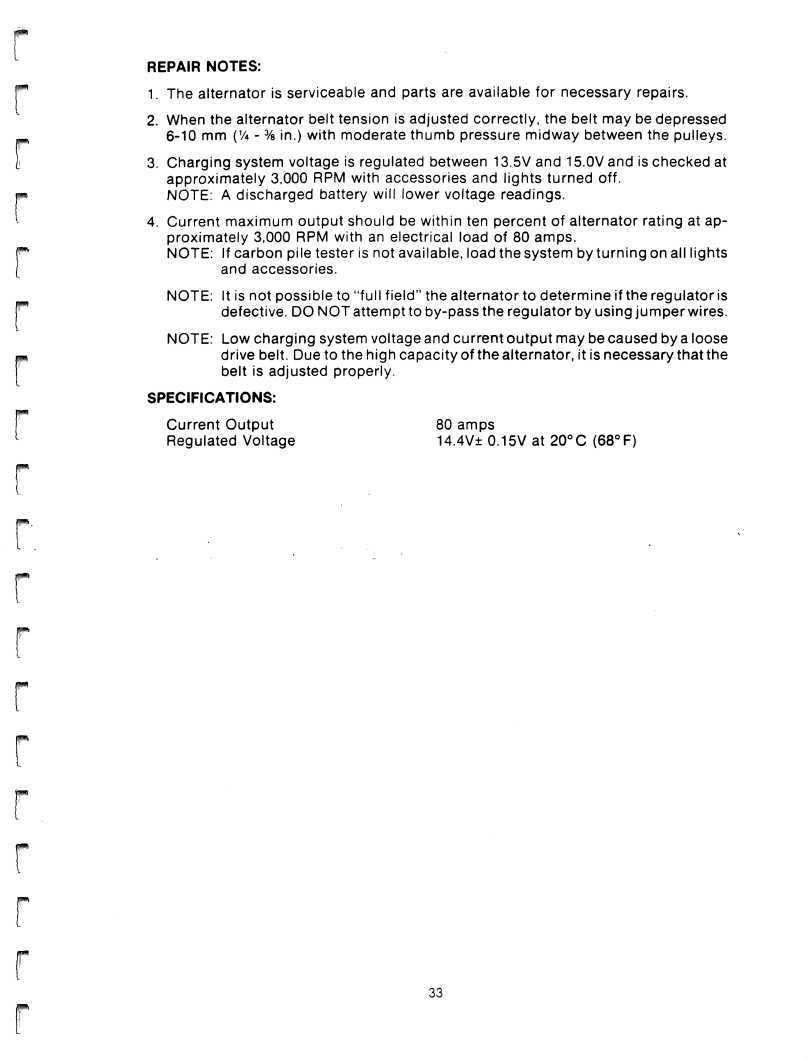
1. The alternator is serviceable and parts are available for necessary repairs. 2. When the alternator belt tension is adjusted correctly, the belt may be depressed _, 6-10 mm (% - % in.) with moderate t h u mb pressure midway between the pulleys. I 3. Charging system voltage is regulated between 13.5V and 15.0V and is checked at approximately 3,000 RPM with accessories and lights turned off. p« NOTE: A discharged battery will lower voltage readings. ^ 4. Current m a x i m um output should be within ten percent of alternator rating at approximately 3,000 RPM with an electrical load of 80 amps. p NOTE: If carbon pile tester is not available, load the system by t u r n i ng on all lights [ and accessories.
NOTE: It is not possible to "full f i e l d" the alternator to determine if the regulator is ™ defective. DO NOT attempt to by-pass the regulator by using j u m p er wires.
NOTE: Low charging system voltage and current o u t p ut may be caused by a loose m drive belt. Due to the high capacity of the alternator, it is necessary that the belt is adjusted properly.
SPECIFICATIONS:
Current Output 80 amps Regulated Voltage 14.4V± 0.15V at 2 0 °C (68°F)

COOLING FAN CIRCUIT
CIRCUIT DESCRIPTION
The De Lorean Sports Car uses a forward mounted radiator fitted with two electric cooling fans to control engine coolant temperature.
A temperature sensor (2), located in the coolant outlet pipe leading to the radiator, cycles the cooling fans (1) on and off to increase air flow through the radiator when coolant temperature increases above normal. The temperature sensor is calibrated to turn the fans on at approximately 97° C (207° F) and turn off when the temperature drops below 91°C (196°F). The fans will remain on continuously if the coolant temperature does not drop below 91 °C. The cooling fan circuit is also controlled by the air conditioning electrical circuit. Whenever the air conditioning compressor is activated, the cooling fans switch on and run continuously to provide constant air flow through the condenser which is mounted in front of the radiator.