3 minute read
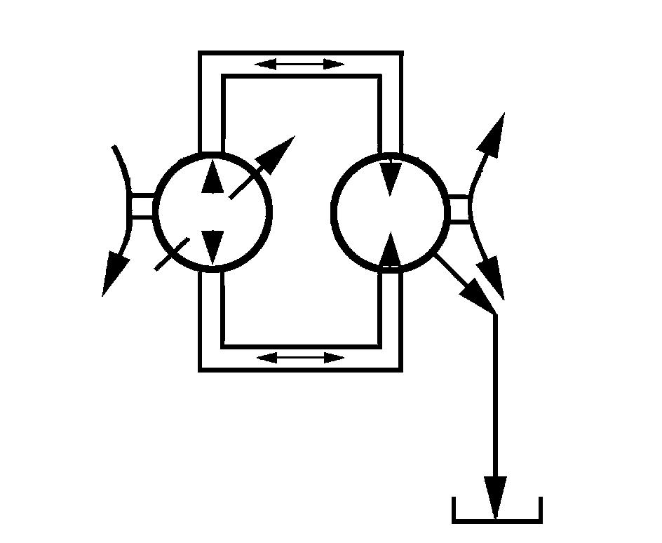
Hydrostatic System

from Daewoo Doosan 430 440 Plus 450 460 Series Hydraulic & Hydrostatic Systems Skid Steer Loader Service
Start-Up Procedure of Hydrostatic System
The following start-up procedure should always be followed when starting up a new installation or when restarting an installation in which either the hydrostatic pump or hydrostatic motor had been removed from the system.
WARNING
The following procedure may require the vehicle to be disabled (wheels raised off the ground, work function disconnected, etc.) while performing the procedure in order to prevent injury to the technician and by-standers.
Prior to installing the hydrostatic pump and/or motor, inspect the units for damage incurred during shipping and handling. Make sure that all system components (tank, hoses, valves, fittings, oil cooler, etc) are clean prior to filling with fluid.
Fill the tank with recommended hydraulic fluid which should be passed through 10 micron filter prior to entering tank.
The inlet line leading from tank to pump must be filled prior to start up. Check inlet line for properly tightened fittings and make sure it is free of restrictions and air leaks.
Be certain to fill the hydrostatic pump and/or motor housing with clean hydraulic fluid prior to start up. Fill the housing by pouring filtered oil into the upper case drain port.
Install a 500 psi (35 bar) pressure gauge in the charge pressure gauge port to monitor the charge pressure during start-up.
With the pump swashplate in its neutral (0 angle) position, “jog” or slowly rotate prime mover until charge pressure starts to rise. Start the prime mover and run at the lowest possible RPM until charge pressure has been established. Excess air may be bled from the high pressure lines through the high pressure gages ports. WARNING
Do not start prime mover unless pump is neutral position (0 swash plate angle). Take precautions to prevent machine movement in case pump is actuated during initial start up.
Once charge pressure has been established, increase speed to normal operation speed. Charge pressure should be 160 psi minimum. If charge pressure is incorrect, shut down and determine the cause for improper pressure.
With motor output shaft disconnected or drive wheels raised off the ground, run system as full input and output speeds in both directions. Operate system for at least 15 minutes.
Shut down prime mover, remove gauge, and plug ports. Check the tank level and add fluid if necessary. The transmission is now ready for operation.
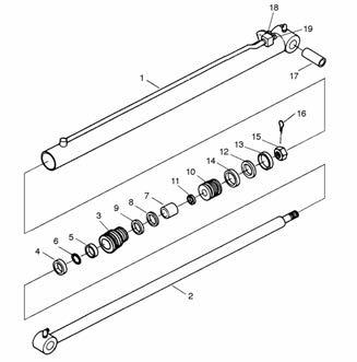
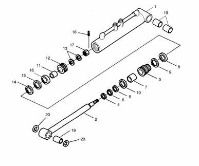
Hydrostatic pump
Gage Installation
It will be necessary to install a high pressure gauge into the system pressure port (or tee into the high pressure line) to check the setting of the system pressure relief valves. Measuring the charging pump inlet vacuum will help locate restrictions in the inlet lines, filter etc. Case pressure readings can help locate restrictions in the return lines, oil cooler, and return filter.
Gauge Connections (Top View)
Gauge Connections (Side View)
D
A Front
B Front B Rear C (With Charge Pump)
D
C
(Less
Charge
Pump) A Rear
IGAT0826I
B Rear (Opposite Side)
B Front
IGAT0827I
Gauge Information
A System Pressure Port “A” 10000 psi (690Bar) gauge 9/16-18 O-ring fitting B System Pressure Port “B” 10000 psi (690Bar) gauge 9/16-18 O-ring fitting C Charge Pressure 500 psi (35Bar) gauge 7/8-14 O-ring fitting D Case Pressure 500 psi (35Bar) gauge 1-1/16-12 O-ring fitting
Direct Displacement Control
Inspect the connection of the control linkage to the swashplate control shaft to insure that the linkage is properly attached. Neutral position of the swashplate is determined by the vehicle control linkage.
Check High Pressure Relief Valves
When a problem occurs in one direction, interchange the charge check or check/relief valves to see if the problem changes to the other direction. If so, one valve is malfunctioning or the check/relief valve cartridge does not have the proper setting pressure.
CAUTION : The relief valves are factory set and should not be tampered with except for replacing the entire cartridge. Disassembly may change the setting and cause erratic unit operation or premature failure.
Pump Charge Relief Valve
If charge pressure is low, the charge relief valve should be inspected. Inspect for foreign material holding the poppet open, and for scoring or wear on the poppet and seat in the housing.
Adjustment of the charge pressure is accomplished by changing the shim thickness behind the spring.
Bypass Valve
The bypass function is accomplished by manually opening the charge check/high pressure relief valves. If the system is operating hot, check that the valves are fully seated by turning the special plugs clockwise with a 5/16” internal hex wrench. Torque the plugs to 30 to 50 ft·lb (41 to 68 N·m).