3 minute read
HST Motor

from Daewoo Doosan 430 440 Plus 450 460 Series Hydraulic & Hydrostatic Systems Skid Steer Loader Service

Since either of the main hydraulic lines can be high pressure, four charge check valves are used to direct the charge supply into the low pressure line. These check valves (located in the pump end cap) also incorporate the high pressure relief valve function. Any charge flow not being used for the closed circuit is discharged over a direct operating charge relief valve, through the pump and motor housings, and back to the tank.
High Pressure Relief Valves
Four combination check /high pressure relief valves are provided in the pump end cap for overload protection. These cartridge type relief valves are factory set, and are not field adjustable.
Direct Displacement Control
The direct displacement control (DDC) is located on either side of the pump, and provides a simple method of control. Movement of the swashplate control shaft produces a proportional swashplate movement and change in pump flow and/or motor shaft speed and direction. The vehicle control system should be designed to return the swashplate to its neutral position.
Bypass Valve
In some applications it is desirable to bypass fluid around the pump allowing, for example, a vehicle to be moved short distance at low speed without running the engine. This is accomplished by manually operated bypass valves incorporated into the charge check/high pressure relief valves in the pump. When open (unscrewed 4 turns maximum), these valves connect both sides of the pump/motor closed circuit, allowing the motor to turn. Both valves must be opened for bypass operation and must be fully closed for normal operation. The engine should be shut down when opening or closing the bypass valves.
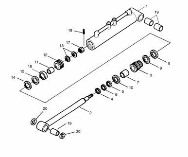
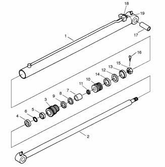
The outer ring of the gear wheel set of HST motor is stationary part of the motor housing. This ring has internal teeth which mesh with teeth on a gear wheel or rotor which rolls inside the ring.
The motion of the rotor is transmitted to the output shaft through a drive. The drive consists of a movable shaft extension with crowned involute splines at either end. These splines match the corresponding tooth system of the output shaft and rotor, resulting in a toothed coupling between rotor and drive and between drive and shaft respectively. As it rotates, the rotor causes continuous opening and closing of tooth spaces. Four of these spaces are subjected to fluid pressure, and the opposed four are connected to return line.
Above pictures show three positions of the rotor, the corresponding rotor center movements, and the locations of pressure and return chambers respectively.
IGAT074IP
Zero Position
1/18 Shaft Rotation
1/9 Shaft Rotation Outer ring
Rotor
As can be seen, the circular movement of the rotor center will cause the shaft to move in the opposite direction at eight times smaller angular velocity.
Hence 1/9 shaft revolution corresponds to 8/9 rotor center revolution causing the oil from 8 fluid chambers to be displaced, i.e. that one shaft revolution gives 8 revolutions of the rotor centre with displacement of 72 chambers.
When used in this way, the gear wheel set thus constitutes a hydraulic motor with a power which is approximately 8 times greater per revolution, compared with hydraulic motors of conventional design. The torque which is approximately 8 times greater is obtained at a speed which is 8 times lower without using a reductions gear.
Furthermore, the displacement of 72 fluid chambers per shaft revolution offers the special advantage of steady operation due to the “smoothing” effect of the increased number of chambers. Above illustrations show the typical example which has one shaft revolution against 6 rotor center revolution with displacement of 42 chambers.
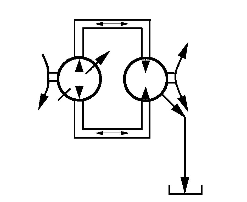
A simple rotary channel plate guides the fluid so that pressure and suction chambers rotate synchronously with the rotor, thus causing continuous rotation.
Above illustrations show the shaft rotation according to flow directions of two main ports of HST motor.
Zero Position Outer ring
IGAT0823P
Rotor
Disc Valve Channel Plate
Revolution of Rotor Center 1/4 Shaft Rotation
1/7 Shaft Rotation
High Pressure Low Pressure
IGAT0821