6 minute read
ASSEMBL Y

from CNH Object handling kit 580ST 590ST 695ST 580T Loader Backhoe Installation Instructions Manual - PDF

2 - KIT CONTENT
Kit overview
Item Description Quantity Part Reference
1 Elbow fitting 1 87675522 2 Rigid pipe 1 84257558 3 Elbow fitting 2 9991973 4 Lock valve 2 87353314 5 Straight fitting 2 201 -111 6 Straight fitting 2 9840534 7 Hose flexible 1 84257430 8 Rigid pipe 1 84352317 9 Union tee 2 84257031 Rigid pipe 1 84358735 11 Hose flexible 1 84257428 Clamp 4 79072960 Connector 1 85805124 Sealing washer 1 47490068 Pressure switch 1 48019154 Cable tie 14560187 Harness, wire, overload 1 48092687 Switch 1 227359A1 Bracket 1 87704587 Buzzer 1 87704586 Harness 1 84262837 Link assembly 1 47950156 Bracket, dipper valve lock 1 47455243 Clamp 2 214 - 1496
W asher 1 86624184 Screw 1 87582902 Nut 1 86619801 28(1) Decal, models,580T and 580ST 1 84236340 28(2) Decal, model 590ST 1 84261481 28(3) Decal, model 695ST 1 84261761 Elbow , 1 48159755 Instruction, installation 1 48161066
3 - PRE-ASSEMBL Y
PREP ARING FOR ASSEMBL Y
Hydraulic systems - Prepare
READ COMPLETE INSTRUCTION SHEET BEFORE INST ALLA TION THIS KIT
NOTICE: The terms right hand and left hand, when used in this instruction, indicate the right and the left sides the machine seen from operators seat.
Reference numbers and letters illustrations are the same reference numbers and letters in the instructions.
Special torque specifications are included in the instructions. torque specifications are not included in the instructions, use standard torque specifications. See your Service Manual Authorized Dealer if you need standard torque specifications.
Preparing for kit component upgrade
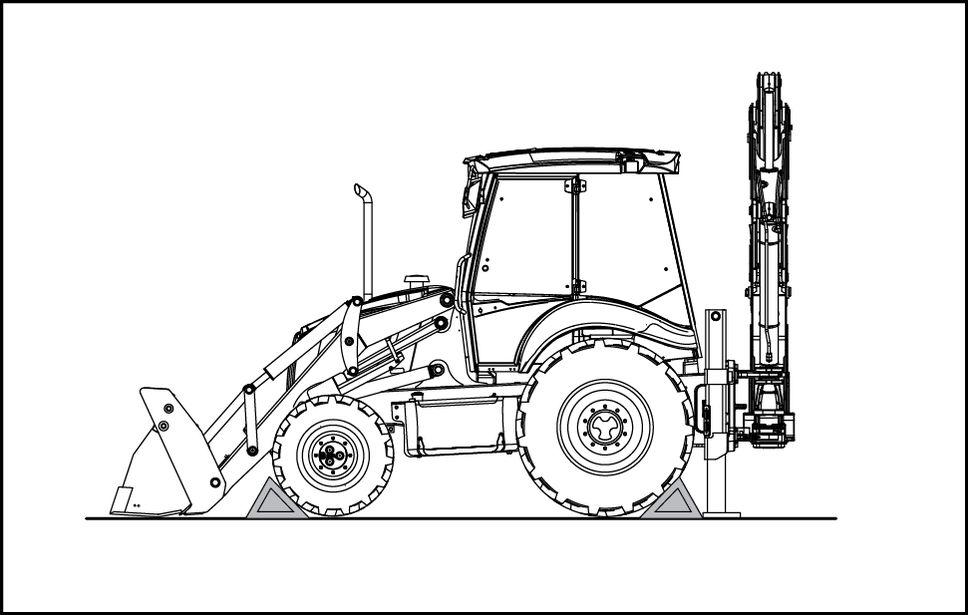
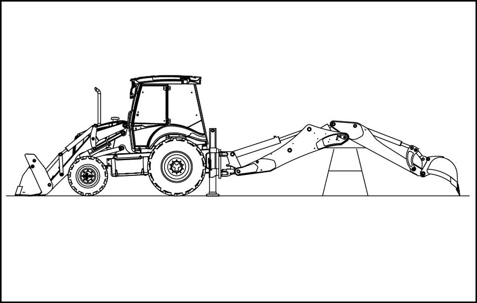
Park the machine a level surface. Place some wedges under the wheels in order prevent the machine from moving. Lower the stabilizers the floor .
Completely extend the dipper and the boom. Lower the boom until the bucket is the floor . Stop the engine and apply the parking brake.
RAIL16TLB1019AA 1
RAIL16TLB1020AA 2
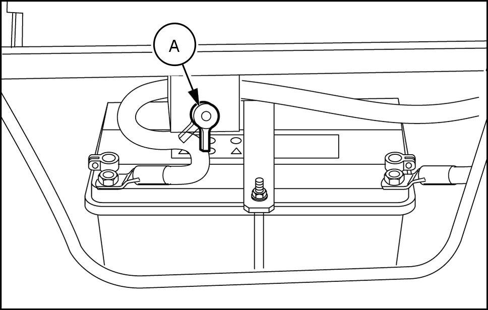
Disconnect the electrical system taking the battery master switch the OFF position. The battery master switch (A) is in the battery compartment. When the battery master switch is in vertical position, the electrical system is connected. When the battery master switch is tilted ° , the electrical system is disconnected.
For Mechanical control machines, move backhoe control levers in all directions release any hydraulic circuit pressure. For Pilot control machines: A. T urn the key the “ON” position and depress the
Pilot Control System switch located the pilot tower . Green light indicating engagement the
Pilot Control System must turn and remain on. B. Move the backhoe control levers in all directions release any hydraulic circuit pressure.
T urn the key “OFF” position.
RAIL16TLB1021AA 3
4 - ASSEMBL Y
Excavator and backhoe hydraulic controls
Installing Kit Components
Mandatory Declaration Conformity updates
NOTE: Hydraulic fluid may released during this procedure, prepared direct fluid into a suitable container and dispose properly . NOTICE: A void contamination, clean all connections before disconnecting tubes, hoses, connectors. Cap plug all ports after disconnecting. A TTENTION: The Dealer the person who guarantees for the correct installation the “Object handling” assembly must certify the correct assembly the Manufacturer , in order ask for the update the EC Declaration Confor mity .
Boom and Dipper Lock V alve Installation
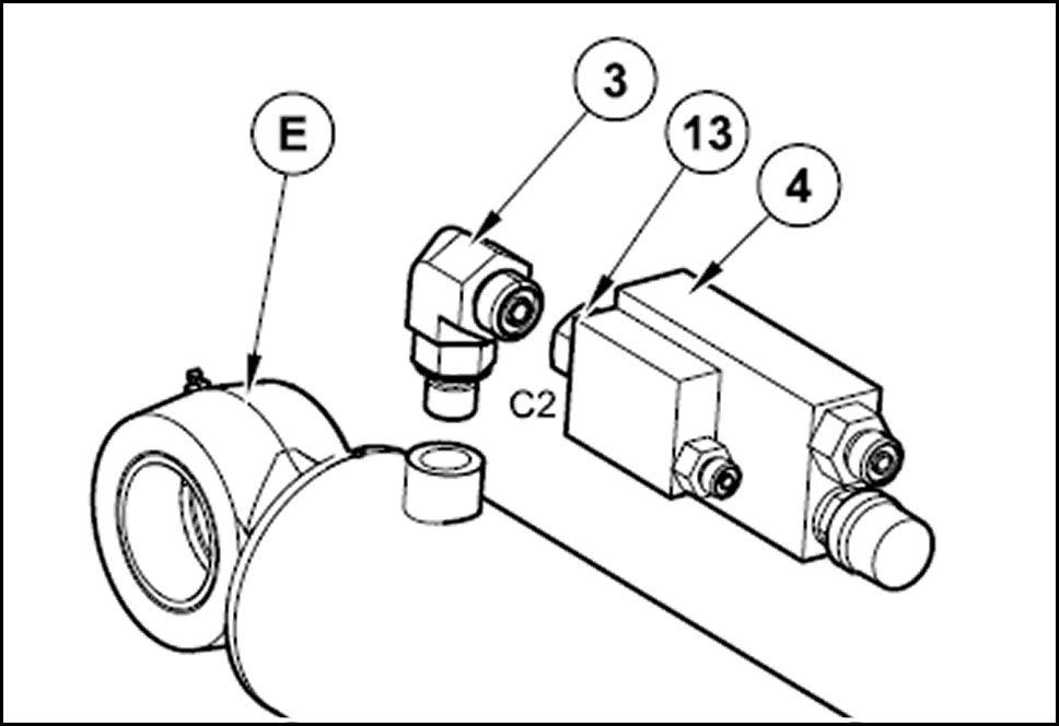
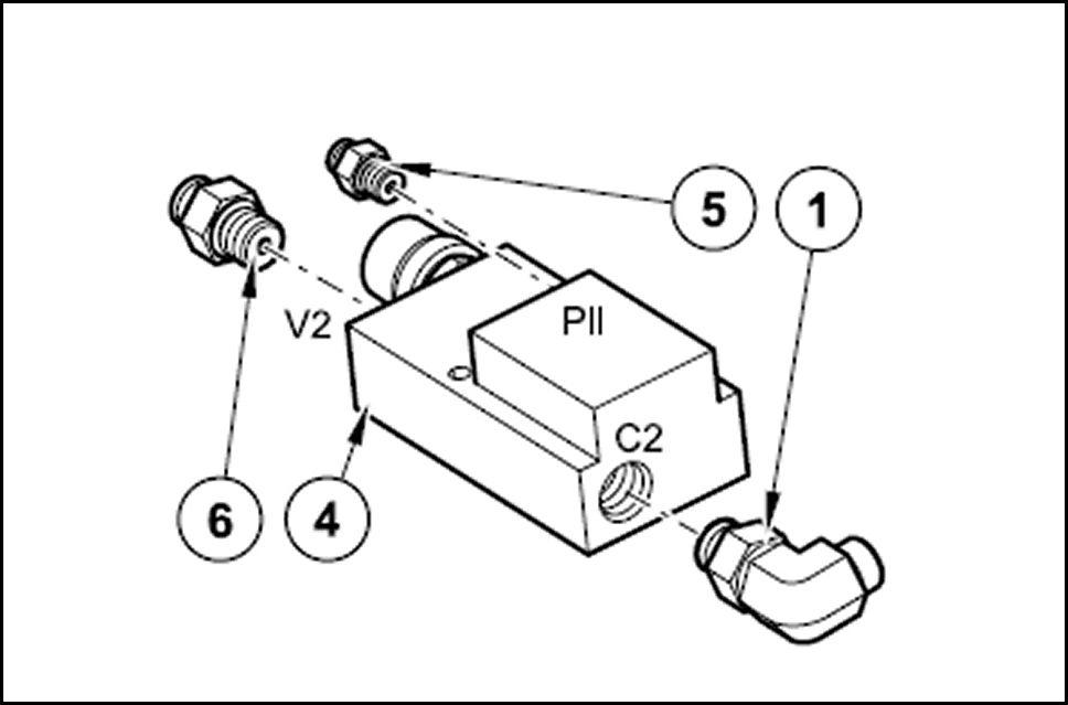
Preassemble the lock valve (4) for the boom cylinder installing the fittings in the valve ports follows:
Install the straight fitting (13) into the port “C2”.
Install the straight fitting (5) into port “V2”.
Install the straight fitting (6) into port “Pil”.
Install the elbow fitting (3) into the boom cylinder (E) the rod side. Install the valve block (4) with its fittings connecting the straight fitting (13) in port “C2” the elbow fitting (3) .

RAIL14TLB0863BA 1
RAIL14TLB0864BA 2
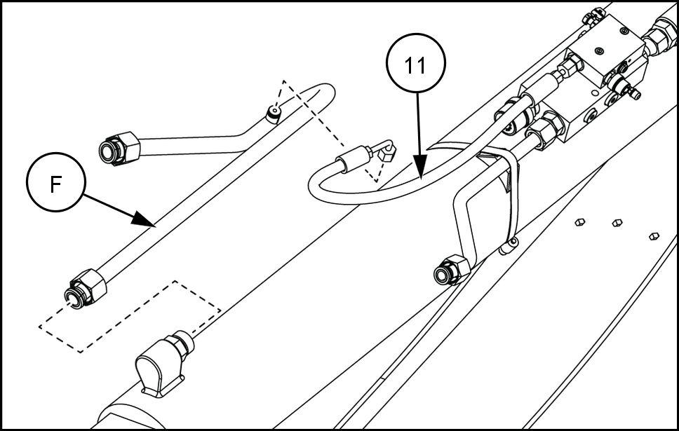
Connect the rigid pipe (10) port “V2” the lock valve (4) . Connect the hose port “Pil” the lock valve (4) . Secure the tube (10) the boom cylinder (E) with the clamp (12) .
Remove and discard the protective plug the tube (F) . Connect the hose the tube (F) .
Secure the tube (F) onto the boom cylinder (E) with the clamp (12) .
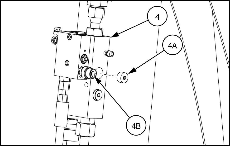
10. Remove the plug (4A) below the oil control valve (4B) the locking valve (4) .

RAIL14TLB0869BA 3
RAIL16TLB0355AA 4

RAIL16TLB0356AA 5
RAIL16TLB0357AA 6
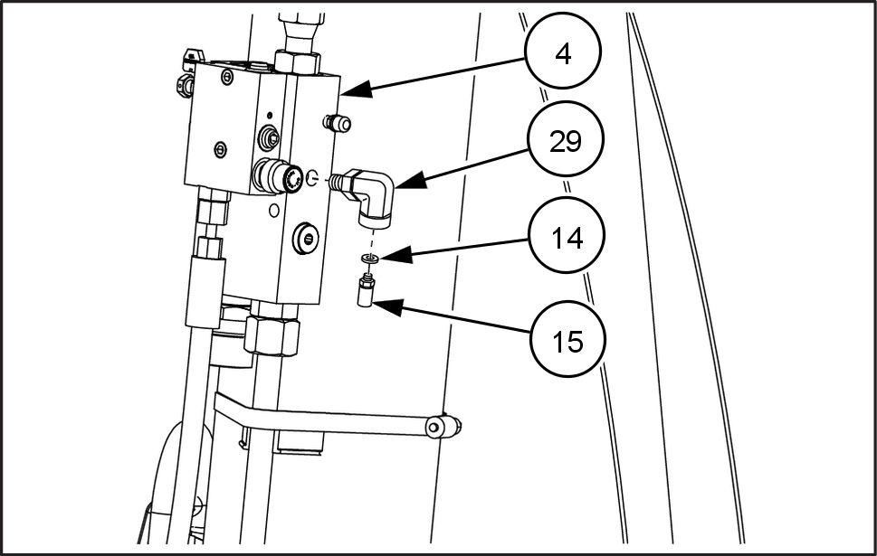
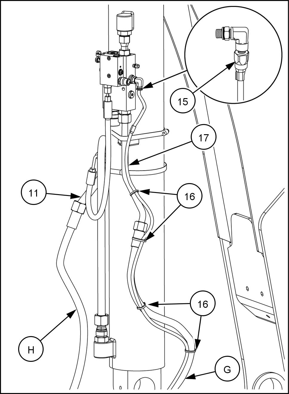
1 Install the elbow (29) , the sealing washer (14) and the pressure switch (15) onto the lock valve (4) . 12. T orque the pressure switch (15) – N·m ( –
).
13. Connect the wiring harness (17) the pressure switch (15) . 14. Connect the hose (G) the tube (10) . 15. Secure the harness (17) onto the hose (G) with the cable ties (16) . 16. Connect the hose (H) the tube .
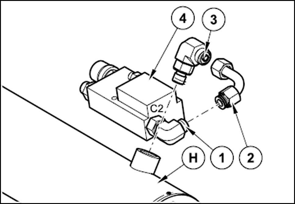
17. Preassemble the lock valve (4) for the dipper cylinder installing the fittings in the valve ports follows:
Install the elbow (1) into port “C2”.
Install the straight fitting (5) into port “Pil”.
Install the straight fitting (6) into port “V2”.
RAIL17TLB0214AC 7
RAIL17TLB0216BD 8
RAIL14TLB0872BA 9
18. Install the bracket (23) onto the lock valve with the bolt (26) , the washer (25) , and the nut (27) .
19. Install the elbow fitting (3) onto the dipper cylinder (H) the rod side. 20. Connect the 90° rigid pipe (2) the elbow fitting (3) . 21. Install the lock valve assembly (4) connecting the elbow fitting (1) in port “C2” the 90° rigid pipe (2) .
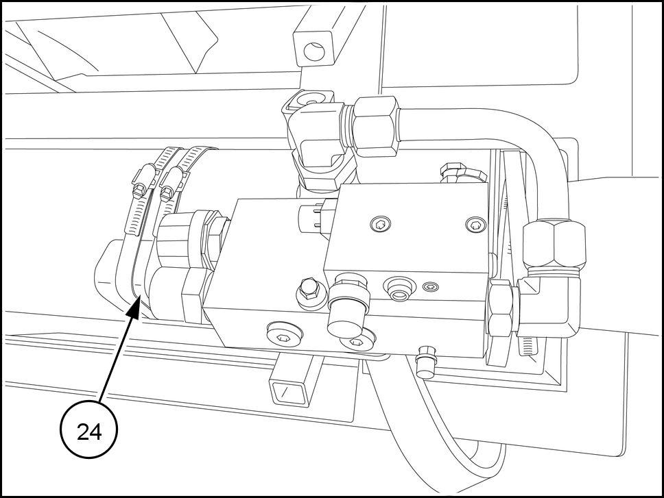
22. Secure the valve the cylinder with the two clamps (24) .

RAPH13TLB0218BA 10
RAIL14TLB0873BA 11
RAIL13TLB0232GA 12
23. Connect the rigid pipe (8) port “V2” the lock valve (4) . 24. Connect the hose (7) port “Pil” the lock valve (4) . 25. Fasten the tubes the dipper cylinder (H) means the 2 clamps (12) .
26. Install the union tee (9) onto the dipper cylinder (H) the piston side. 27. Connect the hose (7) the union tee (9) . Connect the hose (I) , installed the machine, the union tee (9) . 28. Connect the hose (L) , installed the machine, the rigid pipe (8) .
Lift assembly installation
29. Install the link (22) the coupler with the existing pin and the retaining rings.

RAIL14TLB0874BA 13

RAIL14TLB0875BA 14

RAIL14TLB031 1BA 15