4 minute read
ASSEMBL Y

from CNH Joystick Steering with Standard Hydraulic Steering 921G W230D Wheel Loader Instructions Manual

2 - KIT CONTENT
Kit overview
NOTICE: check the items part numbers this kit, please refer the Parts Catalogue. NOTE: the following table shows the items numbered in the installation instruction.
Item Description 2 JSS valve bracket 3 ° elbow 4 ° elbow 5 Straight connector Quantity
1 1 1 2
6 Shuttle tee hydraulic valve 1
7 ° elbow 8 W asher 9x21x2.5 9 Bolt M8x20 T 11 T 1 3 3 3 1
W asher 13.5x28x4 6
Nut M12
3 Bolt M12x50 3 Side rod right hose 435 ( 17.1 ) 1 Side base right hose 545 ( 21.4 ) 1
JSS hose 855 ( 33.7 ) 1 T ank hose 894 ( 35.2 ) 1 JSS pressure hose 880 ( 34.6 ) 1 Load sense hose 900 ( 35.4 ) 1 Cable tie Nut M10 3 Steering angle sensor 1 Straight connector 1 Steering cylinder right head tube 36.2 ( 1.4 ) 1 Clamp block 1 Hose clamp 1 O- ring 1 JSS sensor mounting bracket 1 W asher 9x16x1.6 7 Bolt M8x10 4 JSS frame harness 1 Milsco armrest 1 W asher 10.6x25x6 2 Screw 4 Grammer armrest bracket 1 Bolt M8x20 3 Fuse 5 A 1 EHPS steering valve 1 JSS cut - f valve 1 ° elbow 2 W asher 1 1x21x2.5 6 Bolt M10x105 6 Cylinder hose 1 128 ( 44.4 ) 1 Cylinder hose 1054 ( 41.5 ) 1 Cut - f valve tank hydraulic hose 965 ( ) 1 ° elbow 1 Joystick steering tube 203.1 (8 ) 1 ° elbow 1
Plug 2
3 - GENERAL INFORMA TION ###_1_###
Basic instructions
PLEASE READ THE COMPLETE INSTRUCTIONS BEFORE ARTING ASSEMBL
References right - hand and left - hand are determined standing the rear the machine and facing the direction travel.
NOTE: When referring the instructions for callout references, the numeric (example: (1) ) refers item (1) in the kit contents bill materials. The letter (example: (A) ) refers the component the unit, not a component in the kit contents bill materials. NOTICE: not tighten the hardware until instructed in the assembly instructions.
NOTICE: Be sure use the hardware specified when using tapped holes trying install a metric bolt in inch thread inch bolt in a metric thread will damage the threads.
NOTE: Install flat washers over all slotted holes unless truss - head carriage bolts are used. Install a lock washer all bolts unless a jam nut self - locking nut is specified.
NOTE: Install special hardened washers where specified.
4 - PRE-ASSEMBL Y
PREP ARING FOR ASSEMBL Y
Preparation - Pre - assemble
W ARNING
Crushing hazard! Engage the safety lock link before service transport. Failure comply could result death serious injury .
154A
Preparing
Lower the bucket / attachment the ground, install the transport / service link into the lock position and switch f the engine. Refer the chapter "Safety precautions" contained in the Operator's Manual.
Attach a "DO NOT OPERA TE" maintenance tag. This tag can applied the cab door .
RCPH10WHL063BAL 1
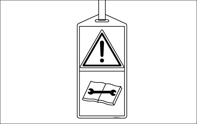
SP0043 2
Removal
NOTE: MARK and LABEL all the various parts (electric connections, hydraulic connections, etc.) before disassembly operations in order facilitate all the reassembly . NOTE: For removal operations, refer Figure 3 and 4.
Remove all dirt and grease under cab (orbitrol and priority valve area).
From load sensing line disconnect and remove the flex hose (A) from orbitrol valve (S) , the ° elbow (D) , and the straight connector (E) installed port “LSST” the priority valve (V) .
Disconnect the hose (B) and the ° elbow (C) from the connector (C1) installed the port “CF” the priority valve (V) . Discard the hose (A) , the connector (E) , the ° elbows (D) and (C) .

LEIL17WHL0410FB 3
Locate the right - hand steering cylinder area and remove the hose clamp (H) , the block (G) , and O- ring (R) .
Disconnect and remove the hose (L) , the union tee (T1) and then the head tube (I) from the right - hand steering cylinder (RH) .
Disconnect and remove the hose (F) , the union tee (T2) from the right - hand cylinder tube (Z) .
Discard the hoses (L) and (F) , the tees (T1) and (T2) , the tube (I) , the hose clamp (H) , the block (G) , and the O- ring (R) .
Under the cab compartment, loosen and remove the four fixing nuts and disengage the orbitrol valve (S) from the steering shaft (SC) .
Remove the four bolts (Q) , the lock washers (P) , the steel mounting bushings (O) , and the rubber bushings (N) unfix the bracket (BR) from the orbitrol valve (S) . 10. Remove the steering isolator (M) .
Discard the four bolts (Q) , the lock washers (P) , the steel bushings (O) , the rubber bushings (N) , the steering isolator (M) and bracket (BR) .