2 minute read
GEARBOX INSTALLATION


DISASSEMBLY
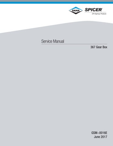
FIGURE 1: Remove fastening screws from the reduction unit.
FIGURE 2: Disjoin the entire reduction unit from the axle and place it on a bench.
NOTE: Carefully remove all residue of Loctite from the surfaces.
This side UP
Inner side

FIGURE 3: Re-introduce the oil shield plate with oil inlet facing upwards. For more details, see "Integrated gear box p.79". FIGURE 4: Assemble the oil shield plate in line with box plane.

FIGURE 5: Assemble the separating snap ring onto the output shaft.
Personal injury can result when installing snap ring. The appropriate safety equipment must be worn. To avoid injury to your eyes, wear protective glasses during this procedure.
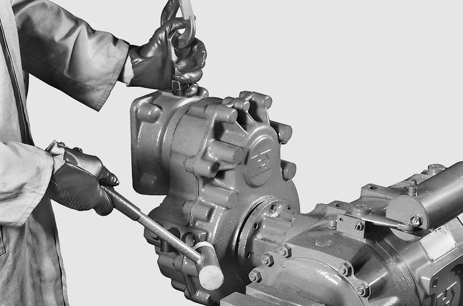
FIGURE 6: Using a normal tool, push the bearing its seat in the cover.

WARNING
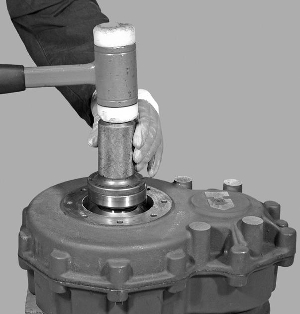


FIGURE 7: Assemble the separating snap ring into the pinion support.
WARNING
Personal injury can result when installing snap ring. The appropriate safety equipment must be worn. To avoid injury to your eyes, wear protective glasses during this procedure.


FIGURE 8: Zero the depth gauge between the cover surface and centering collar.
A
FIGURE 9: Measure distance “A” between snap ring and centering collar. Example: A = 17,10 mm.

B
FIGURE 10: Measure dimension “B” between the bearing and the box plane using an ordinary depth gauge.
FIGURE 11: Work out the difference between the two measures to calculate thickness “S” for shim to be inserted under the bearing so as to obtain the predefined gap. X = gap = 0,15 ± 0,25 mm Example: S = (A - B) - X = (17,10 - 16,80) - 0,20 = 0,10 = S Make up the appropriate pack of shims.
FIGURE 12: Re-assemble the reduction unit onto the axle by spreading Loctite 510 on the planes.
S = (A - B) - X

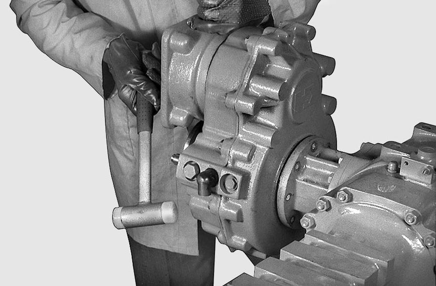
FIGURE 13: Fasten the support planes (turn flange to assist assembly).
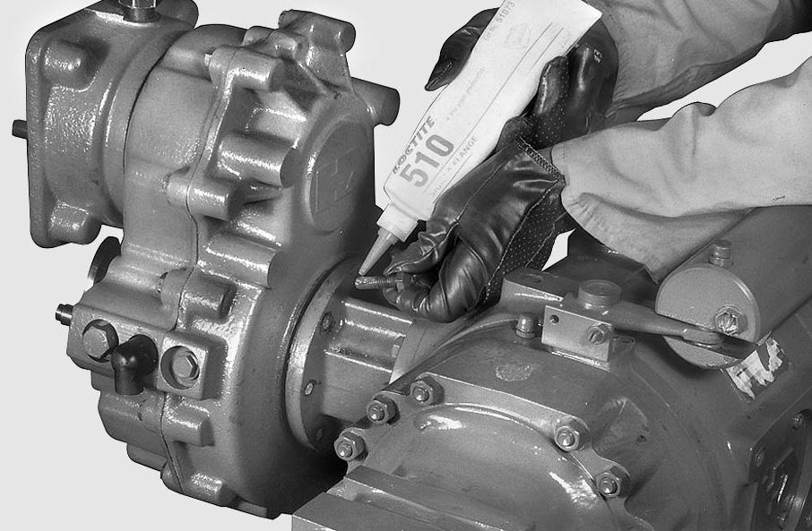
FIGURE 14: Insert screws by applying Loctite 510.
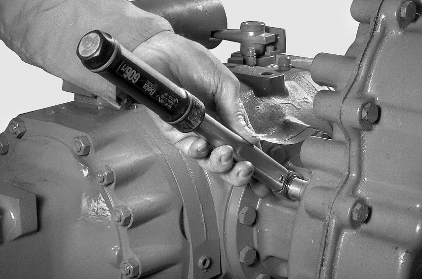
FIGURE 15: Tighten screws using a torque wrench setting of 48-53 N·m.