1 minute read
2.3 Guide rail


Guide rails must be designed to meet the specific application. Loaded trucks can weigh up to 3500 kg and travel at speeds up to 12 km/h. Consequently, a poorly conceived or installed rack system could become a chronic maintenance problem in a short time.
Many effective rail systems are constructed using a common grade of rolled structural steel.
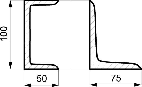
All rail guided trucks can use an angle section of 100 mm x 75 mm x 9 mm (h x w x t) or U-section of 100 mm x 50 mm x 6 mm as a guide rail with normally satisfactory results. Abusive conditions, of course, would call for a more substantial material and anchoring system.
Figure 6. Guide rail cross sections
Installation considerations:
Suggested design for in-aisle guidance: o Rail Section = 100 mm x 75 mm x 9 mm L-section or Rail Section = 100 mm x 50 mm x 6 mmU-section. o Anchor Size = M16, Embedment Depth = 90 mm in 20 MPa concrete (minimum), Spacing = 600mm. Guide rollers must be below the top of any structural guide rail to assure a long life. If over the top, there is a tendency for the roller to ride above the rail with a potential for damaging both rail androller. Rail sections must be welded together and the welds must be grindeddown. Excessive clearance between guide rollers and guide rail can produce rebounding and severe shock loading to both rollers and rail – shortening the life expectancy of both.
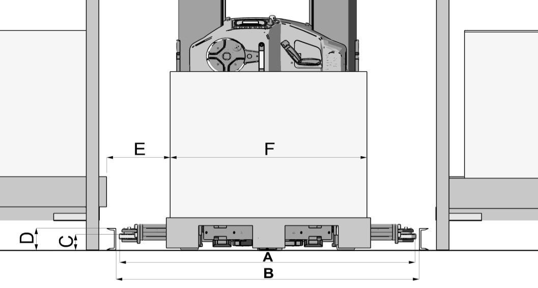
Figure 7. Main dimensions of the rail guided truck