10 minute read
Power


Do not allow the positive cable clamps to contact any metal except for the battery terminals. 9. Connect the other positive end of the jump start cable to the positive cable terminal of the electrical source. 10. Connect one negative end of the jump start cable to the negative cable terminal of the electrical source. 11. Finally, connect the other negative end of the jump start cable to the frame of the stalled machine.
Do not connect the jump start cable to the battery post. Do not allow the jump start cables to contact the following components: the fuel lines, the hydraulic lines, and any moving parts. 12. Start the engine of the machine that is being used as an electrical source or energize the charging system on the auxiliary power source. 13. Wait at least two minutes before you attempt to start the stalled machine. This will allow the batteries in the stalled machine to partially charge. 14. Attempt to start the stalled engine. Refer to
Operation and Maintenance Manual, "Engine
Starting" for the correct starting procedure. 15. Immediately after you start the stalled engine, disconnect the jump start cables in reverse order.
Equipment Lowering with Loss of Hydraulic Power
Lowering the boom with the engine stopped could cause personal injury or death. Keep all personnel away from the boom drop area when lowering the boom with the engine stopped.
Personal injury could result from not following the specified procedure. To avoid personal injury, follow the procedure as specified.
Lowering a raised boom increases the outreach of the load. This could reduce the forward stability of the machine resulting in machine tip over. This could cause injury or death to the operator or other personnel in the work area. Always retract the boom, if possible, before lowering it.
The cylinder for retracting the boom, and the cylinder for lowering the boom are equipped with load control valves. The load control valves lock oil in the cylinders if hydraulic power is lost. The locked oil in the cylinders prevents the boom from moving. In most situations, the boom can be retracted and the boom can be lowered from ground level if hydraulic power is lost. If the angle of the boom is too low you may not be able to retract the boom. If the boom cannot be retracted, it might be possible to lower the load to ground level without retracting the boom first. Assess the weight of the load and consult the appropriate load chart in order to determine that the load can be lowered in this way without causing the machine to tip forward. Do not attempt to lower the boom unless you are satisfied with the stability of the machine. You must be sure that the boom can be lowered without hitting an obstacle. Due to the size of the hydraulic tank, it is possible to return 12 L (3.17 US gal) of oil to the tank more than the tank capacity. This volume of oil must be removed by the following procedure before lowering the boom or retracting the boom from full stroke.
Procedure for Draining Hydraulic Tank
Hot oil and hot components could cause personal injury. Do not allow hot oil or hot components to contact skin.
NOTICE Care must be taken to ensure that fluids are contained during performance of inspection, maintenance, testing, adjusting and repair of the product. Be prepared to collect the fluid with suitable containers before opening any compartment or disassembling any component containing fluids. Refer to Special Publication, NENG2500, "Caterpillar Dealer Service Tool Catalog" for tools and supplies suitable to collect and contain fluids on Caterpillar products. Dispose of all fluids according to local regulations and mandates.
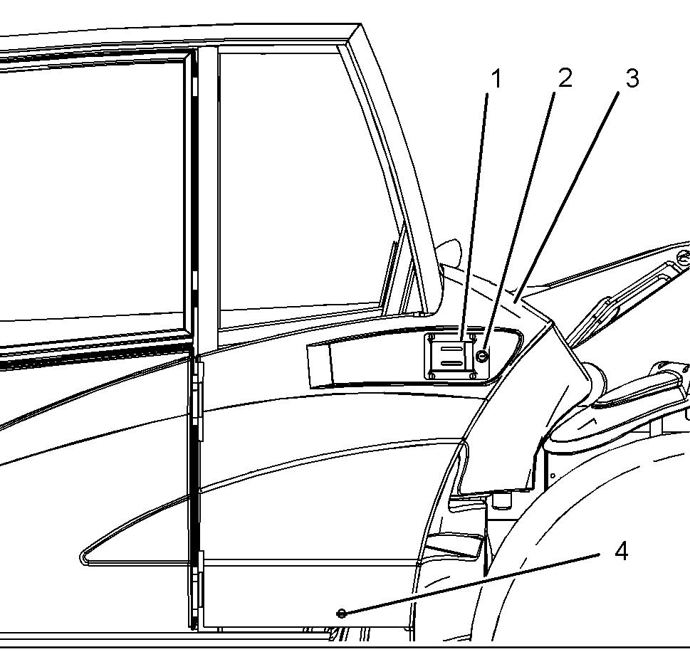
Illustration 141 g01202853 Protection cover
1. In order to open protection cover (3), unlock lock (2) and turn lock (4) counterclockwise. Then, pull latch (1) outward.
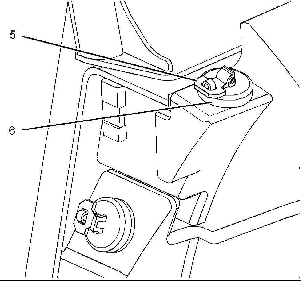
Illustration 142 g01205579 Hydraulic tank filler cap
2. Lift latch (5), and turn the latch counterclockwise in order to relieve the pressure in the hydraulic system. Remove hydraulic tank filler cap (6).

Illustration 144 g01205675
3. Remove drain plug (7) from the bottom of the hydraulic tank and drain 12 L (3.17 US gal) of oil into a suitable container. Clean the drain plug.
Install the drain plug back into the hydraulic tank.
Install the hydraulic tank filler cap. If the boom does not need to be retracted, proceed to "Procedure for Lowering the Boom".
Procedure for Retracting the Boom
Note: If the angle of the boom is below approximately 55 degrees, the boom may not retract. If the boom is below 55 degrees and there is only a light load on the work tool, it may not be necessary to perform "Procedure for Retracting the Boom".
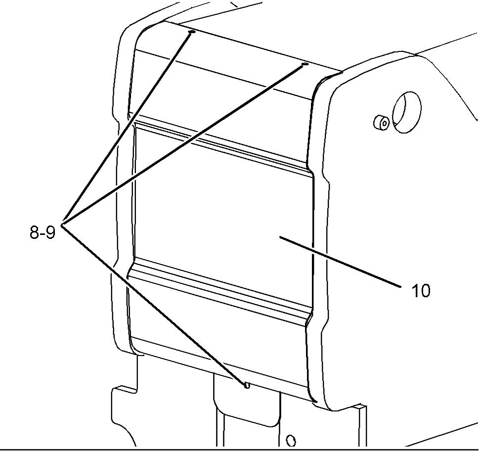

Illustration 145 g01205716
1. Locate the rear cover on the back of the boom.
Remove three bolts (8) and three hard washers (9) that hold rear cover (10) in place. Remove the rear cover.
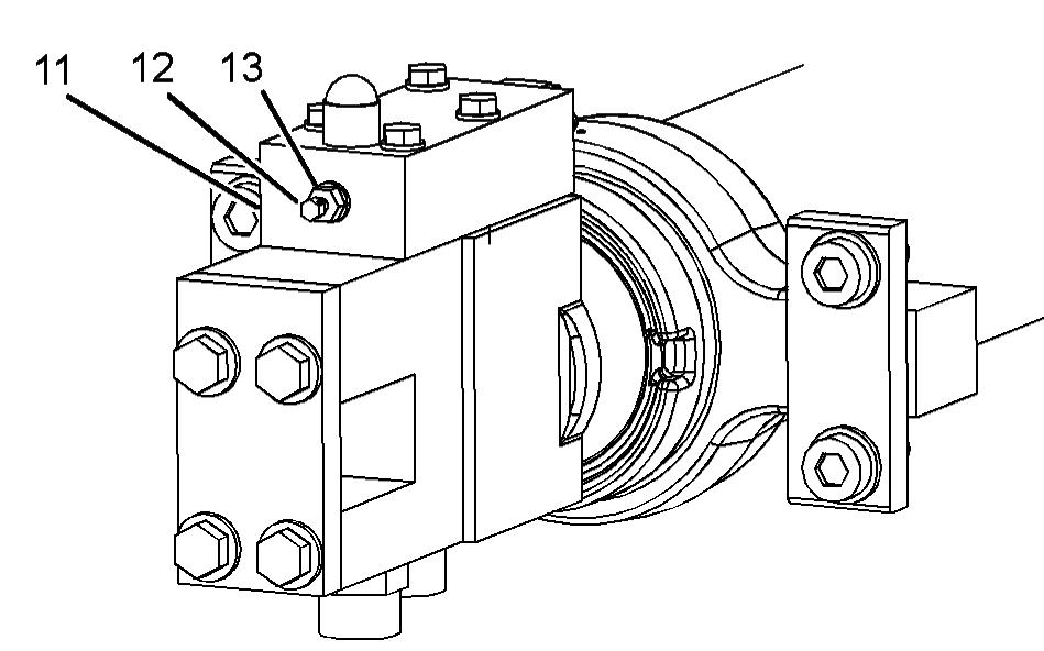
Illustration 146 g01205723
2. Locate load control valve (11). Slightly loosen locknut (13). Remove adjustment screw (12) without rotating locknut (13) on the screw.
Measure the distance from the head of adjustment screw (12) to the top of locknut (13). Record this measurement. This measurement will be required later when adjustment screw (12) is reset. Spin locknut (13) to the head of adjustment screw (12).
Turn adjustment screw (12) by hand into load control valve (11) in order to contact the ball. Attach a wrench to adjustment screw (12) and turn the screw clockwise until the screw becomes tight. Note: Do not use excessive force when a wrench is used in order to turn adjustment screw (12).
Illustration 147 g00964632
3. Locate the rear access cover on the right side of the chassis. Remove the two washers and two bolts that secure the access cover to the chassis.
Remove the access cover in order to gain access to the control valve.
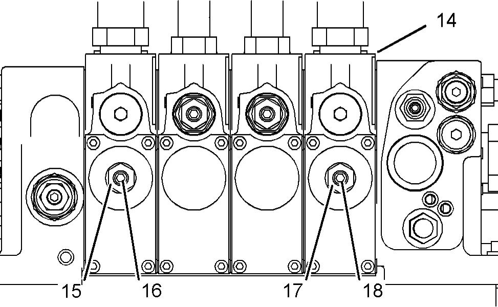
Illustration 148 g01205727
4. Locate control valve (14). 5. Measure the distance from the head of adjustment screw (18) to the top of locknut (17). Completely remove locknut (17). Turn the screw clockwise by hand until the screw is tight. Use an allen wrench to turn the adjustment screw clockwise in order to retract the boom. Allow the boom to fully retract. Note: If necessary, turn adjustment screw (18) counterclockwise in order to stop the boom from retracting. 6. When the boom has fully retracted, turn adjustment screw (18) in a counterclockwise direction until the adjustment screw is returned to the original position. 7. Tighten locknut (17). If the boom needs to be lowered, proceed to "Procedure for Lowering the
Boom". Note: Do not start the engine until you have reset adjustment screws (12) and (18).
8. Start the engine. Raise and lower the boom.
Extend and retract the boom approximately 300 mm (12 inch). 9. Position the boom to the fully retracted position.
Position the boom to the fully lowered position. 10. Remove the hydraulic tank filler cap. Add the 12 L (3.17 US gal) of oil that was removed from the hydraulic tank in Step 3 of "Procedure for Draining
Hydraulic Tank". 11. Check the oil level in the hydraulic tank. If necessary, top up the hydraulic oil to the required level. Install the hydraulic tank filler cap. Clean up any oil that may have been spilled. Refer to
Operation and Maintenance Manual, "Lubricant
Viscosities" and Operation and Maintenance
Manual, "Capacities (Refill)" for further information. 12. Install the access cover on the chassis. Install the rear cover for the boom.
Procedure for Lowering the Boom
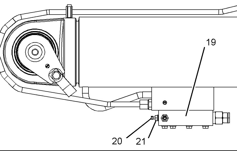
Illustration 149 g01205730
1. Locate load control valve (19) for lowering the boom. The load control valve is mounted to the underside of the cylinder, and toward the rear of the cylinder. The valve can be accessed from the underside of the machine. 2. Slightly loosen locknut (21). Remove adjustment screw (20) without rotating locknut (21) on the screw. Measure the distance from the head of adjustment screw (20) to the top of locknut (21).
Record this measurement. This measurement will be required later when adjustment screw (20) is reset. Spin locknut (21) to the head of adjustment screw (20). Turn adjustment screw (20) by hand into load control valve (19) in order to contact the ball. Attach a wrench to adjustment screw (20) and turn the screw clockwise until the screw becomes tight. Note: Do not use excessive force when a wrench is used to turn adjustment screw (20). 3. Locate control valve (14). Refer to Illustration 148. 4. Measure the distance from the head of adjustment screw (16) to the top of locknut (15). Completely remove locknut (15). Turn the screw clockwise by hand until the screw is tight. Use an allen wrench to turn the adjustment screw clockwise in order to lower the boom. Allow the boom to fully lower. Note: If necessary, turn adjustment screw (16) counterclockwise in order to stop the boom from lowering. 5. When the boom has fully lowered, turn adjustment screw (16) in a counterclockwise direction until the adjustment screw is returned to the original position. 6. Tighten locknut (15). Note: Do not start the engine until you have reset adjustment screw (16) and adjustment screw (20). 7. Start the engine. Raise and lower the boom.
Extend and retract the boom approximately 300 mm (12 inch). 8. Position the boom to the fully retracted position.
Position the boom to the fully lowered position. 9. Remove the hydraulic tank filler cap. Add the 12 L (3.17 US gal) of oil that was removed from the hydraulic tank in Step 3 of "Procedure for Draining
Hydraulic Tank". 10. Check the oil level in the hydraulic tank. If necessary, top up the hydraulic oil to the required level. Install the hydraulic tank filler cap. Clean up any oil that may have been spilled. Refer to
Operation and Maintenance Manual, "Lubricant
Viscosities" and Operation and Maintenance
Manual, "Capacities (Refill)" for further information. 11. Install the access cover on the chassis.
Resetting the Load Control System
Resetting the Load Control Valves
1. Reset adjustment screw (12) to the measurement that was recorded in Step 2 of "Procedure for
Retracting the Boom". Refer to Illustration 146. 2. Reset adjustment screw (20) to the measurement that was recorded in Step 2 of "Procedure for
Lowering the Boom". Refer to Illustration 149. 3. Secure adjustment screw (12) and adjustment screw (20) with locknut (13) and locknut (21). 4. Repair the machine before you return the machine to service.
Purging Air from the System
Air may have entered the hydraulic system. Ensure that the air is purged from the hydraulic system before the machine is returned to service. Note: Purging air from the system should be performed on an unloaded boom. 1. Fully raise the boom and fully lower the boom. 2. Repeat this procedure three times in order to purge the air from the hydraulic system. 3. Fully extend the boom and fully retract the boom.
The boom operation should be smooth. 4. If necessary, repeat this procedure in order to purge the air from the hydraulic system.
Verifying the Correct Setting of the Load Control Valves
1. Install a work tool onto the quick coupler. Raise the boom until the work tool is clear of the ground.
Extend the boom by approximately 300 mm (12 inch). 2. Look at the boom extension reference scale and the boom angle reference scale and note the readings.
Refer to the load chart and use these two values in order to determine the maximum weight that can be lifted with the boom in this position. 3. Pick up the maximum load that was determined in
Step 2. Refer to the procedure for load handling and stacking in Operation and Maintenance
Manual, "Operation Information". 4. Extend the boom approximately 300 mm (12 inch) and fully raise the boom. 5. Stop the engine. 6. On control valve (14), turn locknut (15) and locknut for one turn in a counterclockwise direction. Turn adjustment screw (16) and adjustment screw in a counterclockwise direction for four full turns. Refer to Illustration 148. 7. Check the position of the boom after 10 minutes.
The cylinder for the boom retract and the cylinder for the boom raise should not have drifted. If either cylinder has drifted, consult your Caterpillar dealer.
Do not operate the machine until any necessary repairs are completed or until any necessary adjustments are completed. 8. Turn adjustment screw (16) and adjustment screw (18) in a clockwise direction. Tighten the screws. 9. Tighten locknut (15) and locknut (17).