15 minute read
Work Tools


Proceed with caution when you approach the maximum angle and/or extension indicated by the load chart. If you are not sure that the machine is stable, retract the boom. Lower the load to the travel position. Move the machine closer to the load placement location. If the machine cannot be moved closer to the load placement location, the load placement location is outside the capacity of the machine. The load cannot be placed at the intended load placement location.
Illustration 108 g00832862
16. Tilt the quick coupler forward until the load is level.
Lower and set down the load in place.

Illustration 109 g00832863
17. Ensure that the load is correctly placed and stable.
Use the joystick control to raise the boom and retract the boom in a way that withdraws the forks cleanly from the load. Do not withdraw the forks by backing up the machine.
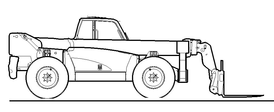
Illustration 110 g00832864
18. Retract the boom and lower the boom to the travel position before you move the machine or before you raise the stabilizers.
General Operating Guidelines
Use of non approved work tools on Telehandler machines could result in injury or death. Before installing a work tool on this machine, ensure that it is approved by Caterpillar and that a Caterpillar load chart covering its use is installed in the machine's cab.
NOTICE When certain work tools are fitted, the work tools can contact the front tires or the front fenders. This situation can occur when the boom is retracted and the work tool is rotated fully forward. Always check for interference when first operating a new work tool.
NOTICE When certain work tools are installed, the work tools can contact the stabilizers. This interference can occur when the boom is retracted and the work tool is rotated fully forward. Always check for interference when first operating a new work tool. Travel with the work tool lowered as far as possible with adequate ground clearance. Travel with the boom fully retracted so that you have good visibility and so that the machine has good stability. Maintain traction by avoiding excessive downward pressure on the work tool. When the machine is operating on a slope, position the heaviest end of the machine uphill.
Make sure that the work tool that is being used is appropriate for the work that is being performed. Exceeding the machine limits will reduce the service life of the machine. Refer to Operation and Maintenance Manual, "Caterpillar Approved Work Tools" for additional information.
Auxiliary Hydraulic Connections
There are many types of work tools from various manufacturers which may be installed on the machine.Caterpillar cannot anticipate every possible work tool and use which may be encountered. When you install a work tool or when you operate a work tool, follow the manufacturer's guidelines and instructions. If you are in doubt, consult your Caterpillar dealer. Your Caterpillar dealer can provide you with further information on the proper installation and use of specific work tools.

Illustration 111 g00975155
On standard machines, a single diverter valve with two quick disconnects is installed. The diverter valve allows the operator to direct hydraulic oil to the hydraulic quick coupler function or to the work tool. Note: The electrical diverter valve may not be installed on certain merchandising arrangements. Consult your Caterpillar Dealer for installation of the connection points for the auxiliary hydraulic service with manual quick couplers. Note: A dual diverter valve is installed as an option. Refer to the topic "Joystick Control" in Operation and Maintenance Manual, "Operator Controls" for more detailed information on operating the boom and the work tools.
Connecting a Work Tool
Refer to the procedures that are described in the topic "Quick Coupler" in Operation and Maintenance Manual, "Operation Information" in order to install the work tools. When you attach work tools that require hydraulic connections, extend the boom by approximately 1 m (3 ft) after installing the work tool onto the quick coupler. This extra space is necessary in order to connect the auxiliary hoses.
1. Position the machine. Rest the quick coupler or the work tool on the ground. 2. Engage the parking brake. Move the transmission control to the NEUTRAL position and stop the engine. 3. The hydraulic controls must be in the HOLD position. The hydraulic controls return to the HOLD position when the hydraulic controls are released. 4. Carefully inspect the hydraulic hoses or pipes on the work tool for any signs of damage. The hydraulic hoses or the pipes must be free of following defects: Cuts, abrasions, bulging, kinking, and dents. Do not use any work tool unless the hydraulic hoses and the pipes are in good condition. 5. Connect the quick disconnects on the work tool to the quick disconnects on the machine. Ensure that the quick disconnects are correctly engaged. The lock rings must be fully engaged and secure.
Disconnecting a Work Tool
1. The work tool must be resting on the ground. If necessary, support the work tool on blocks. 2. Engage the parking brake. Move the transmission control to the NEUTRAL position and stop the engine. Move all the hydraulic controls to the
HOLD position. 3. Clean the quick disconnects. Pull back on the lock rings in order to disengage the quick disconnects.
Install protective caps on the quick disconnects on the machine and on the quick disconnects on the work tool.
Carriages and Forks

Illustration 112 g00974120 Typical carriage and forks
All Caterpillar approved carriages that are used on these machines can be installed directly to the quick coupler. All carriages are designed with backrests to support the load. Wide versions should be used for additional support when large loads are handled.
Forks
A crushing hazard exists when the boom is lowered or from a falling load. Stay clear of the boom when the machine is in operation. Failure to stay clear of the boom could cause injury or death.
Failure to comply to the rated load could cause possible personal injury or attachment damage. Review the rated load of a particular attachment before performing any operation. Make adjustments to the rated load as necessary.
Personal injury or death could result from sudden machine movement. Sudden movement of the machine could cause injury to persons on or near the machine. To prevent injury or death, make sure that the area around the machine is clear of personnel and obstructions before operating the machine.
Refer to the topic "Load Handling and Stacking" in Operation and Maintenance Manual, "Operation Information".
Correct Use of Forks
• Always position the forks into the lifting pockets before you lift a load. • Always position the load over all of the forks so that the weight distribution is even. • Only lift the load if the load is within the loading capacity that is shown on the load chart. The load chart is attached to the dash panel of the machine.
Incorrect Use of Forks
Do not use the forks for any of the following operations:
• Pushing the load or dragging the load • Excavating ground embedded objects • Attaching chains or slings • Lifting a load with only one fork Forks that have been used for any of the applications that are listed above must be removed from the machine. The forks must be destroyed. Note: Slings and chains must be used with a lifting hook.
Buckets
NOTICE When a bucket is used for dozing a site or for clearing a site, keep the bottom face parallel to the ground. This will avoid damage to the leading edge of the bucket. Maintain traction for the machine by avoiding excessive down force on the bucket. Keep the boom extension to a minimum in order to prevent twisting of the boom.
Use a bucket that is suitable for the job.

Illustration 113 g00974741 Typical bucket
Note: The maximum density of material that should be used in a light material bucket is 750 kg/m 3 (46.8 lb/ft3). Buckets that are used in heavy applications are equipped with a cutting edge. General purpose buckets are used for digging and material handling. Typical materials would be earth, sand, cement and aggregates.
Grapple Buckets
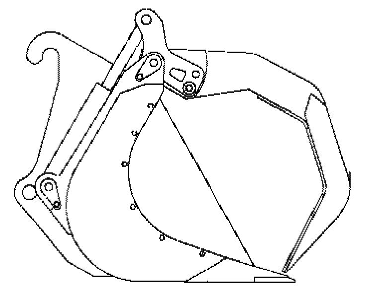
Illustration 114 g00974763 Typical grapple bucket
Grapple buckets are equipped with a cutting edge. Grapple buckets are equipped with hydraulic cylinders that must be connected to the machine hydraulic system. The jaws of the bucket grip the load. For the best operator visibility, travel with the bucket close to the ground. Install the bucket that is appropriate for the intended task. Install the correct wear plate and the correct cutting edge.
Single Thumb Wheel
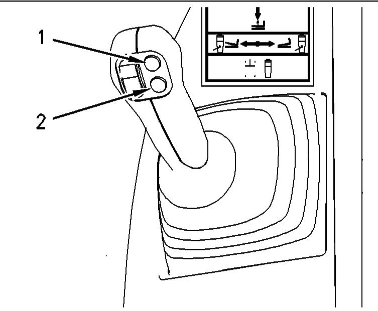
Illustration 115 g00974772
Press and hold switch (1) in order to open the grapple. Press and hold switch (2) in order to close the grapple. Refer to the topic "Joystick Control" in Operation and Maintenance Manual, "Operator Controls" for full information.
Double Thumb Wheel

Illustration 116 g01053965
Move thumb wheel (3) forward in order to open the grapple. Move thumb wheel (3) backward in order to close the grapple. Refer to the topic "Joystick Control" in Operation and Maintenance Manual, "Operator Controls" for full information.
Multipurpose Buckets

Illustration 117 g01037342 Typical multipurpose bucket
Multipurpose buckets are equipped with a cutting edge. For the best operator visibility, travel with the bucket close to the ground. Install the bucket that is appropriate for the intended task. Install the correct wear plate and the correct cutting edge.
Boom Extension

Illustration 118 g00974780
A boom extension is intended to be used in applications when additional reach or height is required in order to place light loads such as supports for roofs. Reference the correct load chart and do not exceed the machine capacities. Use only approved lifting equipment with a current certificate of serviceability when you attach a load to a boom extension. Short slings will prevent excessive load swing. Before you raise the load, position the lifting point on the boom extension directly above the lifting point on the load. Failure to follow this procedure could cause the load to swing when the load is lifted. Personal injury or damage to surrounding structures and materials could result. Extremely cold temperatures could cause a load to be frozen to the ground. Free the load before you attempt to raise the load. Failure to comply could affect the stability of the machine when a lift is attempted. Use tag lines to assist in the control of loads that require accurate placement. When a load is lifted and the boom is extended and raised, the boom will deflect under the load. This has the effect of moving the load away from the machine as the load is raised. Make an allowance for this deflection. Maneuver the load into position by operating the boom functions. Do not use the quick coupler to position the load when the boom extension is installed. The operator must remain at the controls of the machine when a load is suspended from the boom extension.
Lifting Hook
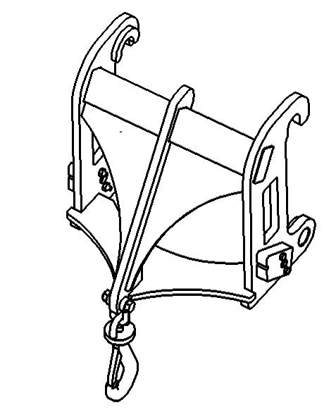
Illustration 119 g00974785
Before you raise the load, position the lifting point on the lifting hook directly above the lifting point on the load. Failure to follow this procedure could cause the load to swing when the load is lifted. Personal injury or damage to surrounding structures and materials could result.
Material Handling Arm

Illustration 120 g01037376
Reference the correct load chart and do not exceed the machine capacities. Use only approved lifting equipment with a current certificate of serviceability when you attach a load to a material handling arm. Short slings will prevent excessive load swing.
Before you raise the load, position the lifting point on the material handling arm directly above the lifting point on the load. Failure to follow this procedure could cause the load to swing when the load is lifted. Personal injury or damage to surrounding structures and materials could result. Extremely cold temperatures could cause a load to be frozen to the ground. Free the load before you attempt to raise the load. Failure to comply could affect the stability of the machine when a lift is attempted.
Use tag lines to assist in the control of loads that require accurate placement. When a load is lifted and the boom is extended and raised, the boom will deflect under the load. This has the effect of moving the load away from the machine as the load is raised. Make an allowance for this deflection. Maneuver the load into position by operating the boom functions. Do not use the quick coupler to position the load when the material handling arm is installed.
Hopper
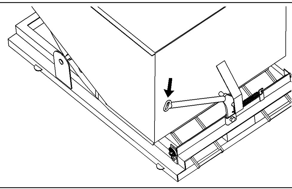
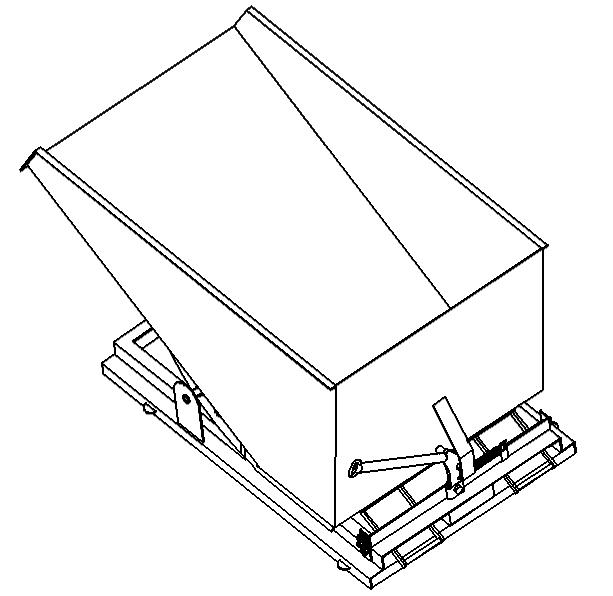
Illustration 121 g00974787
Picking up the Hopper
Position the machine square to the hopper. Extend and lower the boom. The forks must enter the pockets of the hopper cleanly. The forks must be fully engaged with the pockets of the hopper.

Illustration 122 g00974805
When the forks fully engage, a bar that is spring loaded will lock each fork in position. Establish that the forks are securely locked in place before you raise the hopper. Before you raise the hopper, ensure that the latch for the trip lever is securely engaged. Raise the hopper. Tilt the quick coupler slightly backward in order to better secure the hopper. Travel with the boom fully retracted so that you have good visibility and so that the machine has good stability.
Discharging the Hopper
Travel the machine to the work area. Stop the machine and apply the parking brake. Lower the hopper.
Illustration 123 g00974801
Pull down on the release lever. The hopper will tilt forward and the load will be discharged. To remove the hopper, lower the hopper to the ground. The bar that secures the forks in place will automatically disengage when the hopper is placed on the ground. Withdraw the forks from the pockets by retracting the boom.
Utility Fork with Grapple and Ejector

Illustration 124 g00974838 The forks are used to tear out material from a pile. The fork with the grapple has the same function as the fork. The grapple is used for increased load retention. The ejector dumps the load more efficiently.
Picking up a Load
When you load a fork, the boom must be fully retracted. Raise the forks in order to clear the ground.
Single Thumb Wheel
Illustration 125 g00974772
Press and hold switch (1) in order to open the grapple. Release the switch when the grapple is fully open. Approach the load with the grapple in the fully open position. Drive the forks into the load to the desired position. Press and hold switch (2) on the joystick control in order to close the grapple over the load. Release the switch when the grapple is fully closed. Refer to the topic "Joystick Control" in Operation and Maintenance Manual, "Operator Controls" for additional information.
Double Thumb Wheel
Illustration 126 g01053965 Move thumb wheel (3) forward in order to open the grapple. Release the thumb wheel when the grapple is fully open. Refer to the topic "Joystick Control" in Operation and Maintenance Manual, "Operator Controls" for full information. Approach the load with the grapple in the fully open position. Drive the forks into the load to the desired position. Move thumb wheel (3) backward in order to close the grapple over the load. Release the thumb wheel when the grapple is fully closed. Refer to the topic "Joystick Control" in Operation and Maintenance Manual, "Operator Controls" for additional information.
Ejecting a Load
Position the load over the intended dump area.

Illustration 127 g00974863
Single Thumb Wheel
Illustration 128 g00974772
Press and hold switch (1) in order to open the grapple. Continue to hold switch (1) after the grapple has fully opened in order to operate the ejector. Note: The ejector will only operate when the grapple is fully open. When the load has been ejected, press and hold switch (2) on the joystick control in order to retract the ejector. Continue to hold switch (2) after the ejector has fully retracted in order to close the grapple. Note: The grapple will only close when the ejector is fully retracted. Refer to the topic “Joystick Control” in Operation and Maintenance Manual, “Operator Controls” for full information.
When the work tool is not active, position the fork so that personnel cannot contact the fork tines.
Double Thumb Wheel
Illustration 126 g01053965
Move thumb wheel (3) forward in order to open the grapple. Continue to hold thumb wheel (3) after the grapple has fully opened in order to operate the ejector. Note: The ejector will only operate when the grapple is fully open. When the load has been ejected, move thumb wheel (3) backward in order to retract the ejector. Continue to hold thumb wheel (3) after the ejector has fully retracted in order to close the grapple. Note: The grapple will only close when the ejector is fully retracted. Refer to the topic "Joystick Control" in Operation and Maintenance Manual, "Operator Controls" for full information. When the work tool is not active, position the fork so that personnel cannot contact the fork tines.
Bale Handler

Illustration 130 g00974880
Single Thumb Wheel
Illustration 131 g00974772
Press and hold switch (1) on the joystick control in order to open the prongs. Press and hold switch (2) on the joystick control in order to close the prongs. Refer to the topic "Joystick Control" in Operation and Maintenance Manual, "Operator Controls" for full information.
When the work tool is not active, position the bale handler so that personnel cannot contact the prongs.