15 minute read
Operation Information


Removal
Note: Follow the same mounting and dismounting guidelines that are detailed in the installation section. 1. Install the engine start key. If equipped, install the battery disconnect switch key. Start the engine.
Slowly raise the boom until boom plates (6) are clear of location tongue (5). Stop the engine. If equipped, remove the battery disconnect switch key. Remove the engine start switch key. 2. Remove retaining clip (3) and pin (2). Remove boom cylinder lock (1) from boom cylinder and place the lock on the flat area of the main frame.
Descend from the machine.
Illustration 83 g01071445 Typical example of storage bracket
3. Stow boom cylinder lock onto the storage bracket that is mounted on the machine. The bracket can be mounted on the left side of the machine or on the right side of the machine. 4. Install the engine start key. If equipped, install the battery disconnect switch key. Start the engine and fully lower the boom.
Do not operate or work on this machine unless training has been accomplished and you have read and understand the instructions and warnings in the Operation and Maintenance Manuals. Failure to follow the instructions or heed the warnings could result in injury or death. Contact your Caterpillar dealer for replacement manuals. Proper care is your responsibility. If the machine is positioned too close to electric power lines, electric current will pass through the machine. This will cause injury or death by electrocution. Keep the machine at least 8 m (25 ft) away from electric power lines. Always check for power lines before raising the boom.
The instability of the machine could result in injury or death. In order to ensure the stability during operation, the following conditions must be observed. The tires must be inflated correctly and the tires must have the correct amount of ballast (if equipped). The machine must be level. The frame level switch must never be operated when the boom is raised. The frame level switch must never be operated when the stabilizers are lowered. The switches for the stabilizers must never be operated when the boom is raised. The correct load chart must be referenced for the work tool that is installed on the machine. The specified weights and load centers must never be exceeded. The machine must never be moved when the boom is raised above the carry position.
If equipped, use the frame leveling control in order to level the machine on uneven ground. Use the level indicator in order to verify that the frame is level. Level the frame before you lift a load. Never operate the frame leveling control when you have raised the boom. Always use the boom in order to engage the load with the work tool. Do not move the machine in order to engage the load with the work tool. Always use the boom in order to position the load with the work tool. Do not move the machine in order to place the load with the work tool. Always use the boom in order to disengage the load from the work tool. Do not move the machine in order to disengage the load from the work tool. Operate the boom smoothly in order to avoid damaging or dislodging the load. Do not move the machine while the boom is raised or while the boom is extended. If it is necessary to reposition the machine, lower and retract the boom first. The transmission neutralizer switch operates in conjunction with the service brake. The switch must be in the OFF position when you travel on the roadways. Do not use the machine for lifting loads in tandem with other machines. The combined load weight and force of the other machine can exceed machine capacity. This could cause the machine to turn over.
Ensure that the correct machine load capacity chart is used for the work tool that is installed. Ensure that you use the correct machine load capacity chart for operation on tires. Make sure that you understand the machine load capacity chart before you attempt to lift a load. Be alert at all times for changing conditions which may affect the stability of the machine. Extending the boom or lowering the boom increases the outreach of the load. This decreases the capacity and the stability of the machine. Retract the boom before you lower the boom. Be careful when you position a load or when you engage a load. Be careful when you are using clamps or when you are using cylinders. Also, be careful when you are using a device that pierces the load. Ensure that the operation can be completed without pushing the load off the stack. Note: Refer to Operation and Maintenance Manual, "Operator Controls" for the location and operation of the machine controls. 1. Make sure that no one is on the machine or near the machine before you move the machine. Keep the machine under control at all times. 2. Start the machine. 3. Raise all lowered work tools in order to pass over any obstacles. Fully raise the stabilizers. 4. Push down on the service brake control in order to prevent the machine from moving. 5. Disengage the parking brake. The parking brake has an interlock switch which prevents the machine from being driven through the brake. The machine will not move in forward or in reverse when the parking brake is engaged. 6. Move the transmission control to FORWARD position (F) or to REVERSE position (R). 7. Rotate the transmission control until the required transmission speed is selected. 8. In order to move the machine, release the service brake pedal. Push the accelerator control.
Changing Speed and Direction

Illustration 84 g01042565 Transmission control
Start moving the machine with the machine in first gear or in second gear. To upshift, rotate the transmission control to the next highest gear. It is not necessary to release the accelerator control. To downshift, rotate the transmission control to the next lowest gear. Do not skip gears when you downshift. Continue to shift through the gears in this way as the conditions are required. To prevent engine overspeed, do not downshift if the engine speed is high. Refer to the topic "Transmission Control" in Operation and Maintenance Manual, "Operator Controls" for additional information. Control the speed of the machine in order to suit conditions. Make an allowance for surface conditions, weather conditions and load.
NOTICE Damage to the transmission could occur if the machine is allowed to coast in neutral. Damage to the transmission could also occur if a change of direction is selected while the machine is moving. Do not allow the machine to coast. Only select a transmission direction change if the machine is completely stopped.
Note: These machines are not equipped with speedometers. Before you change the direction of the machine from forward to reverse or from reverse to forward stop the machine completely. Select the correct gear before you travel downhill. Select the necessary travel speed before you start downhill. Do not change gears while you are going downhill. When you go downhill, use the same speed that would be used to go uphill. Do not allow the engine to overspeed when you go downhill. Use the service brake to prevent engine overspeed when you go downhill. Select a lower gear before you go down the same hill again.
When you are travelling uphill, select a lower gear when the engine speed starts to fall. Drive the machine in the gear that will allow the required speed to be maintained.
Hydraulic Quick Coupler
Your machine may be equipped with a hydraulic quick coupler. Illustrations in the following procedure show a carriage which is equipped with forks. The procedure is applicable to all work tools with the same types of mounting points.
Installation Procedure

Illustration 85 g01060075
1. Move the red portion of the switch for the quick coupler downward and press the top of the switch.
Hold the top of the switch until the quick coupler pins are fully disengaged. Release the switch. 2. Lower and extend the boom approximately 2 m (6.6 ft) so that the quick coupler can be seen from the cab. Position the quick coupler in line with the carriage.

Illustration 86 g00975380
3. Tilt the quick coupler forward until the quick coupler tubes (1) are below the level of hooks (2).

Illustration 87 g00975278
4. Extend the boom slowly until the quick coupler tubes contact the carriage. Raise the boom until the quick coupler tubes are engaged with the hooks.
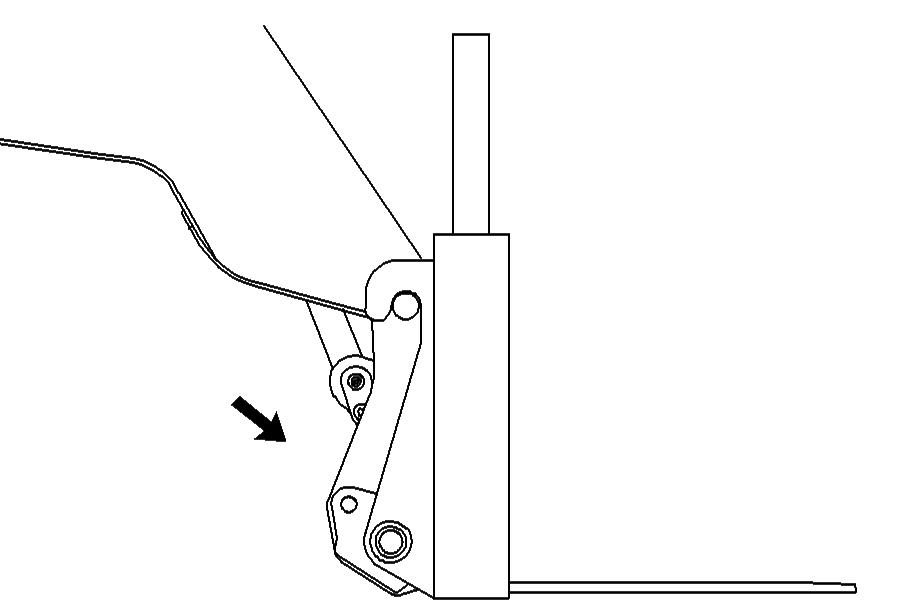
Illustration 88 g00975332
5. Tilt back the quick coupler until the lower part of the carriage is in contact with the quick coupler. 6. Press and hold the bottom of the switch for the quick coupler in order to engage the quick coupler pins. Release the switch after the pins are fully engaged.
An improperly installed work tool could become dislodged from the machine during operation. This could cause injury or death. Do not operate the machine until you have positive indication that the quick coupler pins are fully engaged.

Illustration 89 g00975388 Left quick coupler pin
7. Check the positions of the pins on both sides of the quick coupler. Both quick coupler pins must be fully engaged. Lower the boom until the carriage is pressed against the ground. Slowly back up the machine. As the machine starts to move, check for movement between the carriage and the quick coupler. Movement indicates that the pins for the quick coupler are not properly installed. Do not operate the machine unless the pins for the quick coupler are fully engaged through the quick coupler and the carriage. 8. If equipped, install the hydraulic lines for the carriage to the diverter valve.
Removal Procedure
1. Tilt back the quick coupler. Lower and extend the boom approximately 2 m (6.6 ft) so that the quick coupler can be seen from the cab. 2. If equipped, disconnect the hydraulic lines for the attachment from the changeover valve.
Illustration 90 g01060075
3. Move the red portion of the switch for the quick coupler downward and press the top of the switch.
Hold the top of the switch until the quick coupler pins are fully disengaged. Release the switch. 4. Lower the boom and tilt the quick coupler forward until the carriage is on the ground. If necessary, block the carriage in order to prevent the carriage from moving when the carriage is disengaged from the quick coupler. Lower the boom until tubes (1) are disengaged from hooks (2). Retract the boom until the quick coupler is clear of the carriage.
Manual Quick Coupler
Your machine may be equipped with a manual quick coupler. Illustrations in the following procedure show a carriage which is equipped with forks. The procedure is applicable to all work tools with the same types of mounting points.
Installation Procedure
1. 1. Lower and extend the boom approximately 2 m (6.6 ft) so that the quick coupler can be seen from the cab. Position the quick coupler in line with the carriage.

Illustration 92 g01060117
2. Remove the retaining clip from pin (3). Remove the pin. 3. Tilt the quick coupler forward until the quick coupler tubes (1) are below the level of hooks (2).
Illustration 93 g00975278
4. Extend the boom slowly until the quick coupler tubes contact the carriage. Raise the boom until the quick coupler tubes are engaged with the hooks.
Illustration 94 g00975332
5. Tilt back the quick coupler until the lower part of the carriage is in contact with the quick coupler. 6. Install pin (3) and the retaining clip. 7. Install auxiliary hydraulic hoses or control cables to the machine (if equipped).
Removal Procedure
1. Extend the boom approximately 2 m (6.6 ft) so that the carriage is just clear of the ground and visible from the cab. Tilt back the quick coupler. Disconnect the hydraulic lines or cables for the carriage from the boom head (if equipped).
Illustration 95 g01060117
2. Remove the retaining pin and remove pin (3). 3. Lower the boom and tilt the quick coupler forward until the carriage is on the ground. If necessary, block the carriage in order to prevent the carriage from moving when the carriage is disengaged from the quick coupler. Lower the boom until tubes (1) are disengaged from hooks (2). 4. Retract the boom until the quick coupler is clear of the carriage. 5. Install the pin into the coupler.
Use of Work Tools
NOTICE When certain work tools are fitted, the work tools can contact the front tires or the front fenders. This situation can occur when the boom is retracted and the work tool is rotated fully forward. Always check for interference when first operating a new work tool.
When you use a blade to level or when you use a blade to scrape, the boom must be fully retracted. Operate with the bottom of the blade parallel to the ground. A number of Caterpillar approved buckets are included as work tools for telehandlers. Reference the correct load chart for the work tool that is installed and never exceed the weights and load centers that are specified in the load charts. When you load a bucket the boom must be fully retracted. Extending the boom increases the outreach of the load, which will reduce the forward stability of the machine. Note: If an adapter for a work tool is installed on the quick coupler, reduce the load carrying capacity of the machine by 200 kg (440 lb) for all work tools and with the boom in any position.
NOTICE To avoid damage to the boom during digging and/or backgrading operations, keep the boom fully retracted.
Take material from the stockpiles in a way which avoids undercutting the pile or creating an overhang.
Load Handling and Stacking
The illustrations that follow show a machine that is equipped with a work tool carriage. The work tool carriage is an example of a work tool that can be mounted on the quick coupler.

1. The machine must be positioned square to the intended load. Approach the load slowly with the boom in the travel position and get as close to the load as possible. 2. Engage the parking brake and move the transmission control to the NEUTRAL position. 3. If necessary, level the frame before you raise the boom or before you engage the load. Do not level
the frame when the boom is raised.

Illustration 97 g00832850
4. If you are operating with stabilizers, lower the stabilizers until the front tires are just clear of the ground and the frame is level.

Illustration 98 g00832851
5. Tilt the quick coupler until the forks are level. The machine is equipped with an automatic system for keeping the quick coupler at the selected angle when the boom is raised or lowered.

Illustration 99 g00832852
6. Ensure that the forks are spread apart as far as possible. This gives increased stability to the load.

Illustration 100 g00832853
7. Raise the boom and extend the boom. The forks must be in line with the pockets of the load. 8. Use the load chart to assess the intended load.
The load chart must indicate that the intended load is within the capacity of the machine. Refer to
Operation and Maintenance Manual, "Lifting
Capacities".

Illustration 101 g00832854
9. Extend and lower the boom. The forks must enter the pockets of the load cleanly. The forks must be fully engaged with the pockets of the load. Take care not to dislodge the load.

Illustration 102 g00832856
10. Raise the load carefully. When you are sure that the machine is stable, tilt the quick coupler backward in order to raise the load. If you are not sure that the machine is stable, tilt the quick coupler forward in order to lower the load. Do not proceed.
Reposition the machine in order to shorten the reach before you attempt to lift the load again.

Illustration 103 g00832857
11. Use the joystick control to move the load away from the stack.

Illustration 104 g00832858
12. Retract the boom and lower the load to the travel position before the machine is moved or before the stabilizers are raised. If necessary, level the frame.
Make sure that the area behind the machine is clear of personnel and obstacles before backing up.
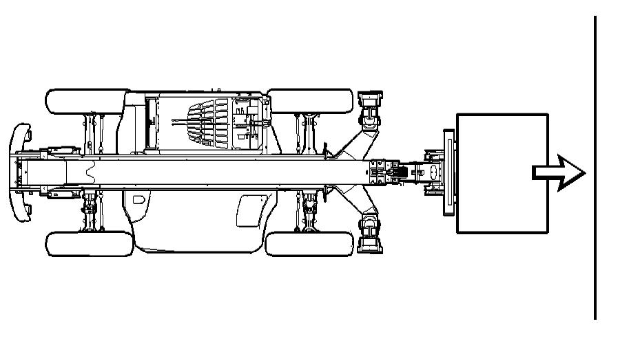
Illustration 105 g00832859
13. Approach the destination slowly. Position the machine square. Get as close to the load placement location as possible. Engage the parking brake and move the transmission control to
NEUTRAL position. If necessary, level the frame.
Do not level the frame when the boom is raised.

Illustration 106 g00832860
14. If you are operating with stabilizers, lower the stabilizers until the front tires are just clear of the ground.

Illustration 107 g00832861
15. Raise the boom and extend the boom until the load is directly over the set down position. Do not exceed the maximum angle of the boom and do not exceed the maximum length of the boom. Use the load chart to determine the maximum angle of the boom and the maximum length of the boom.