33 minute read
Operator Controls


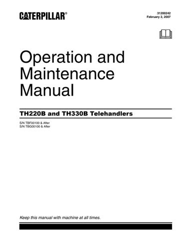
Illustration 56 1. Horn 2. Auto/Manual switch (if equipped) 3. Quick coupler control 4. Transmission neutralizer control 5. Steering mode control 6. Reversible fan control 7. Frame leveling control 8. Continuous auxiliary flow control 9. Fog lights 10.Hazard flashers 11.Headlight dimmer switch 12.Headlight-Parking lights 13.Rotating beacon light 14.Joystick control 15.Adjustable armrest 16.Side console 17.Interior light 18.Parking and secondary brake control 19.Accelerator control 20.Service brake control 21.Differential lock control 22.Transmission control
g01213443

Illustration 57 g01147794
23.Directional turn signal control 24.Engine start switch 25.Steering column tilt control
Note: Your machine may not be equipped with all of the controls that are described in this topic.
Horn (1)
Horn - Horn (1) is located in the center of the steering wheel. Push horn (1) in order to sound the horn. Use the horn in order to alert personnel. Also, use the horn in order to signal personnel.
Auto/Manual Switch (2)
Auto/Manual Switch - This is a two-position switch. If your machine is equipped with the Powersynchro transmission this switch is an option on your machine. Push the left side of the switch in order to select automatic shifting between the gears of the transmission. The operator will select the highest speed range and the machine ECM will automatically shift the transmission between the lowest gears to the highest gear that has been selected, based on ground speed of the machine. A lamp inside the switch will be illuminated. Push the right side of the switch in order to manually select a specific speed gear.
Quick Coupler Control (3)
Quick Coupler Control - This is a three-position switch, if equipped. When switch (3) is released the switch will return to the HOLD position.
Disengage - Move the red slider on switch (3) downward, and push the top of switch (3). Hold the top of switch (3) until the quick coupler pins are fully disengaged. Hold - When switch (3) is released the switch will return to the HOLD position. Engage - Press the bottom of switch (3). Hold the bottom of switch (3) until the quick coupler pins are fully engaged.
Transmission Neutralizer Control (4)
If the transmission neutralizer control switch is in the ON position and the service brake control pedal is pressed, the transmission will shift into NEUTRAL. When the service brake control pedal is released it will take a short period of time for the transmission to reengage the original gear. If the machine is on a hill during this time, the machine can roll forward or the machine can roll backward. The unexpected movement of the machine could cause personal injury or death. Refer to Operation and Maintenance Manual, "Transmission Control" for additional information.
Transmission Neutralizer Control - This is a two-position switch, if equipped. Push the top of switch (4) in order for the transmission neutralizer to be operational. A lamp inside switch (4) will be illuminated. The transmission will be neutralized whenever the service brake is applied. Push the bottom of switch (4) in order for the transmission to remain engaged whenever the service brake is applied.
Steering Mode Control (5)
Personal injury or death could result if the machine is roaded in any mode other than two-wheel steer. Always road the machine with the rear wheels centered and the machine in the two-wheel steer mode.
NOTICE To avoid possible damage to the steering system, always center the rear wheels before operating the machine in the two-wheel steer mode. It is important to check the alignment of the wheels at least once per day. Failure to do this may result in reduced accuracy in the steering system.
Steering Mode Select Switch - This threeposition switch controls the steering mode. Push the top of switch (5) in order to select crab steer. Set switch (5) to the middle position in order to select circle steer. Push the bottom of switch (5) in order to select two-wheel steer. Note: Always move the front wheels and the rear wheels to the straight ahead position before you change the steering modes.

Illustration 58 g01053683
Circle Steer Mode - When circle steer mode is selected, indicator (5A) is illuminated.
Crab Steer Mode - When crab steer mode is selected, indicator (5B) is illuminated.
Two-Wheel Steer Mode - When two-wheel steer mode is selected, indicator (5C) is illuminated.
Use of Steering Modes
The machine can be operated in the following steering modes: • Two-Wheel Steer • Circle Steer • Crab Steer Only the front wheels are steered in two-wheel steer mode. This mode must be used when you road the machine. When the machine is in circle steer mode, the front wheels and the rear wheels turn in opposite directions. This allows the machine to make tighter turns. When the machine is in crab steer mode, the front wheels and the rear wheels turn in the same direction. When you select the crab steer mode, the machine will move forward and the machine will move to one side. Alternatively, the machine will move backward and the machine will move to one side. This allows the machine to operate in confined locations.
Checking or Synchronizing the Wheels Machines with Steer Sensors
1. In a static position, select circle steer mode and ensure that the circle steer mode indicator is constantly illuminated. Adjust the steering wheel, as required. 2. Select two-wheel steer mode and ensure that the two-wheel steer mode indicator is constantly illuminated. Adjust the steering wheel, as required. 3. Select your desired steer mode and use as normal.
Machines without Steer Sensors
1. In a static position, select circle steer mode. By using your eyes, align the rear wheels to a straight position. 2. Select two-wheel steer mode. By using your eyes, align the front wheels to a straight position. 3. Select your desired steer mode and use as normal. Note: It is important not to try to turn the steering wheel once the ignition is turned to the OFF position. This can lead to steer misalignment, which will result in reduced accuracy of the steering system.
When you change the steering mode, it is possible for the steering to go out of synchronization. This will happen under the following conditions: • The rear wheels are not positioned straight when you change from circle steer mode to two-wheel steer mode. • The rear wheels are not positioned straight when you change from crab steer mode to two-wheel steer mode. • All four wheels are not positioned straight when you change from circle steer mode to crab steer mode. • All four wheels are not positioned straight when you change from crab steer mode to circle steer mode.
Use the following procedure in order to synchronize the steering: 1. 1. Stop the machine while either crab steer mode or circle steer mode is selected.

Illustration 59 g00603627
2. Turn the steering wheel until the left rear wheel is in line with the side of the machine.
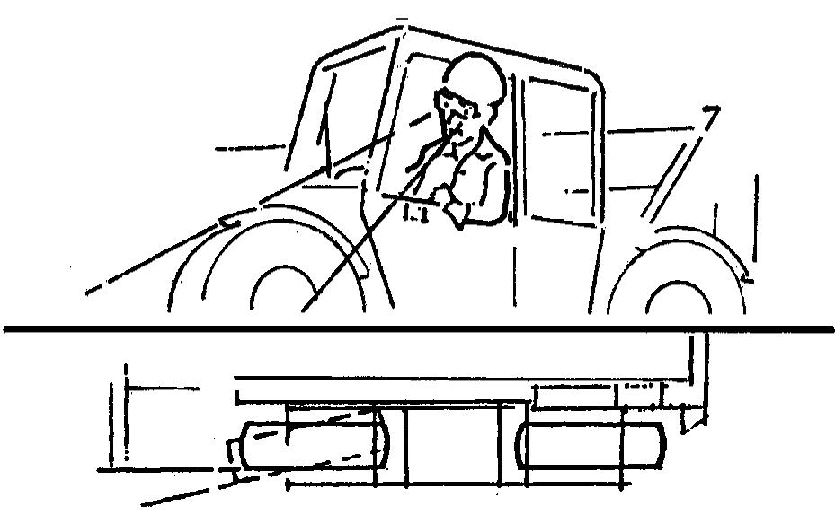
Illustration 60 g00603632
3. Change to two-wheel steer and turn the steering wheel until the left front wheel is in line with the side of the machine. 4. Change to either crab steer mode or circle steer mode, as required.
Your machine may be equipped with self-aligning rear steering. The self-aligning feature ensures that the rear wheels are aligned before the steering mode is changed. When switch (5) is pressed by the operator, the machine will not change to the desired steering mode unless the rear wheels are in the straight ahead position. If switch (5) is pressed by the operator and the rear wheels of the machine are not aligned, the current steering mode will remain selected. The indicator for the current steering mode on the display panel will remain on, and the desired mode indicator will flash. When the rear wheels are moved to the straight ahead position by the operator, the steering mode will then change to the desired mode.
Reversible Fan Control (6)
Reversible Fan Control - If equipped, switch (6) is a momentary toggle switch. The reversible fan control reverses the rotation of the cooling fan in order to remove debris from the radiator grill. The fan is reversed by depressing switch (6). When switch (6) is released, the cooling fan will return to the normal rotation.
NOTICE Before operating the reversible fan control, ensure that the machine is in an area clear of personnel and other objects that may be effected by the airborne debris blown from the radiator grill.
Engage the parking brake and move the transmission control (22) to the NEUTRAL position. Depress switch (6) only when the engine speed is less than 1000 rpm. The engine speed can be increased while the fan is operating in the reverse direction. The engine speed must be reduced to less than 1000 rpm before switch (6) is released. Note: Do not hold the switch for more than thirty seconds at a time.
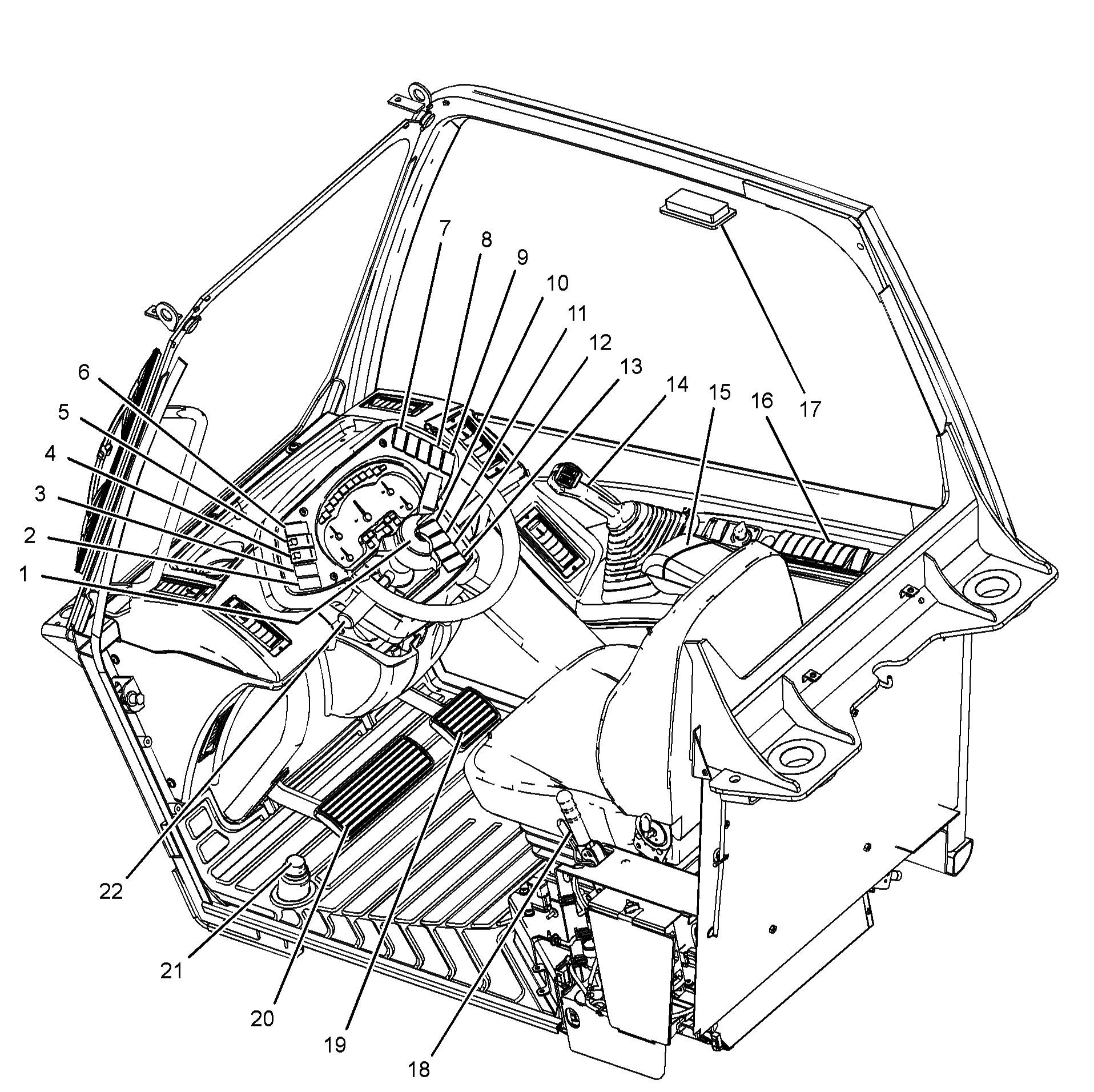
Frame Leveling Control (7)
If equipped, frame leveling control (switch) (7) is a three-position switch. The frame leveling control is used to level the machine when the machine is on an uneven surface. The frame leveling control can cause the frame to tilt to the left or to the right. The maximum amount of tilt is 10 degrees in either of these directions. Lower the boom before you use the frame leveling control. The boom must be close to the ground. Press the right side of switch (7) in order to lower the right side of the frame. The frame rotates clockwise. Press the left side of switch (7) in order to lower the left side of the frame. The frame rotates counterclockwise. When switch (7) is released, the frame leveling control returns to the HOLD position. Use the level indicator to determine when the frame is level. The frame is level when the bubble is in the middle of the sight glass.
When the boom is extended outward, the frame level will be isolated. The operator will not be able to use the frame level function until the boom has been fully retracted. The operation of the Frame Level Interlock will not affect any other functions of the machine hydraulics.
If equipped, switch (8) is a momentary toggle switch. Depress switch (8) when the auxiliary hydraulics are being operated. This will provide continuous flow to the auxiliary hydraulics. The button on joystick (14) that is pressed will determine the direction of flow. In order to resume normal operation, depress switch (8) again. Alternately, press one of the buttons on the joystick. Normal operation will resume.
Depress switch (8) when the auxiliary hydraulics are being operated. This will provide continuous flow to the auxiliary hydraulics. The direction of movement of the right thumb wheel on joystick (14) will determine the direction of flow. The flow rate is fixed when continuous flow is requested. In order to resume normal operation, depress the switch again. Alternately, move the right thumb wheel upward or move the right thumb wheel downward. Normal operation will resume.
Fog Lights (9)
lights. Fog Lights - Push the right side of switch (9) in order to turn on the fog lights. Push the left side of switch (9) in order to turn off the fog
Hazard Flashers (10)
Hazard Flashers - Push the right side of switch (10) in order to activate the hazard flashers. All the turn signal lights will flash simultaneously. Push the left side of switch (10) in order to deactivate the hazard flashers.
Headlight Dimmer Switch (11)
Dimmer Control - Push the right side of switch (11) in order to activate the high beam headlights. Switch (12) for the headlights must be in the HEADLIGHTS position in order to activate the high beam. The headlights remain on high beam until the left side of switch (11) is pushed to the LOW BEAM position.
Headlight-Parking Lights (12)
Low Beam Headlights - Push the right side of switch (12) in order to turn on the parking lights and the rear lights. Push the right side of switch (12) again in order to turn on the headlights, the parking lights and the rear lights. Push the left side of switch (12) in order to turn off the headlights. Push the left side of switch (12) again in order to turn off the parking lights and the rear lights.
Rotating Beacon Light (13)
Rotating Beacon (if equipped) - Push the right side of switch (13) in order to activate the rotating beacon. Push the left side of switch (13) in order to deactivate the rotating beacon.
Joystick Control (14)
Improper use of the boom and work tools could result in injury or death. The operator must be fully aware of all the functions for the joystick control and proper operating techniques.
The following information describes two types of operating arrangement for the joystick control. A decal that shows the configuration is located forward of joystick control (14). The decal indicates the movements that will be produced when you operate the joystick control.
You must understand all of the functions of the joystick control before you operate the machine.
Type A Control Arrangement (Single Thumb Wheel)

Illustration 61 g01147843
Machines that have the Type A control arrangement are equipped with decal (14A) that is shown above. Joystick control (14) operates in the following way:

Illustration 62 g01213550
Boom Raise - Pull joystick control (14) backward in order to raise the boom. When joystick control (14) is released, the joystick control will return to the HOLD position.
Boom Lower - Push joystick control (14) forward in order to lower the boom. When joystick control (14) is released, the joystick control will return to the HOLD position.
Quick Coupler (Tilt Forward) - Push joystick control (14) to the right in order to tilt the quick coupler forward. When joystick control (14) is released, the joystick control will return to the HOLD position. Quick Coupler (Tilt Backward) - Push joystick control (14) to the left in order to tilt the quick coupler backward. When joystick control (14) is released, the joystick control will return to the HOLD position.
Boom Extend - Push thumb wheel (14B) forward in order to extend the boom. When the thumb wheel is released, the thumb wheel will return to the HOLD position. Note: The boom will not extend when the transmission control is in the REVERSE position. The function for extending the boom will resume if the transmission is neutralized by the service brake, the parking brake, or the transmission neutralizer button.
Boom Retract - Pull thumb wheel (14B) backward in order to retract the boom. When the thumb wheel is released, the thumb wheel will return to the HOLD position.
Auxiliary Controls - Press switch (14E) in order to toggle between the hydraulic circuits for the auxiliary 1 and auxiliary 2. Press switch (14C) in order to operate an actuator for a work tool in the positive direction. Press switch (14D) in order to operate an actuator for a work tool in the negative direction. Switches (14E), (14C) and (14D) are not operated proportionally.

Illustration 63 g01147848
When auxiliary 2 is selected, indicator light (14G) will be illuminated. The speed of the following functions is governed by the amount of movement of the joystick control and engine speed: • Boom raise • Boom lower • Quick coupler (tilt forward) • Quick coupler (tilt backward)
For smooth operation, first increase the engine speed from low idle. Then, move joystick control (14) slowly until the attachment is moving at the required speed. The speed of the boom extend and boom retract is governed by the amount of movement of thumb wheel (14B). Move joystick control (14) diagonally in order to simultaneously tilt the quick coupler forward or backward while the boom is being raised or lowered. Move joystick control (14) diagonally. At the same time operate thumb wheel (14B) in order to simultaneously tilt the quick coupler while the boom is being operated in two directions.
Type A Control Arrangement (Double Thumb Wheel)
Illustration 64 g01147850 Decal for joystick with double thumb wheel
Machines that have the Type A control arrangement are equipped with decal (14A) that is shown above. The joystick control operates in the following way:
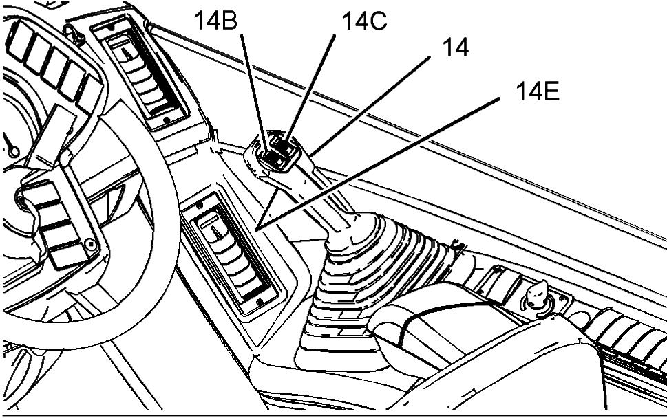
Illustration 65 g01213551 Boom Raise - Pull the joystick control backward in order to raise the boom. When the joystick control is released the joystick control will return to the HOLD position.
Boom Lower - Push the joystick control forward in order to lower the boom. When the joystick control is released the joystick control will return to the HOLD position.
Quick Coupler (Tilt Forward) - Push the joystick control to the right in order to tilt the quick coupler forward. When the joystick control is released the joystick control will return to the HOLD position.
Quick Coupler (Tilt Backward) - Push the joystick control to the left in order to tilt the quick coupler backward. When the joystick control is released the joystick control will return to the HOLD position.
Boom Extend - Move thumb wheel (14B) forward in order to extend the boom. When the thumb wheel is released the thumb wheel will return to the HOLD position. Note: The boom will not extend when the transmission control is in the REVERSE position. The function for extending the boom will resume if the transmission is neutralized by the service brake, the parking brake, or the transmission neutralizer button.
Boom Retract - Move thumb wheel (14B) backward in order to retract the boom. When the thumb wheel is released the thumb wheel will return to the HOLD position.
Auxiliary Controls - If equipped, press switch (14E) in order to toggle between the hydraulic circuits for the auxiliary 1 and auxiliary 2. Move thumb wheel (14C) forward in order to operate an actuator for a work tool in the positive direction. Move thumb wheel (14C) backward in order to operate an actuator for a work tool in the negative direction. Switch (14E) is not operated proportionally.
Illustration 66 g01147848
When auxiliary 2 is selected, indicator light (14G) will be illuminated. The speed of the following functions is governed by the amount of movement of the joystick control and engine speed: • Boom raise • Boom lower • Quick coupler (tilt forward) • Quick coupler (tilt backward) For smooth operation, first increase the engine speed from low idle. Then move joystick control (14) slowly until the attachment is moving at the required speed. The speed of the boom extend and boom retract is governed by the amount of movement of thumb wheel (14B). Move joystick control (14) diagonally in order to simultaneously tilt the quick coupler forward or backward while the boom is being raised or lowered. Move joystick control (14) diagonally. At the same time operate thumb wheel (14B) in order to simultaneously tilt the quick coupler while the boom is being operated in two directions.
Type B Control Arrangement (Single Thumb Wheel)
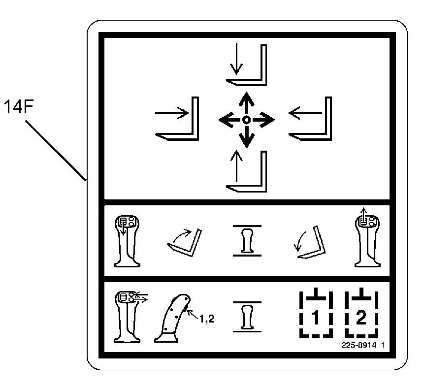
Illustration 67 g01147854
Machines that have the Type B control arrangement are equipped with decal (14F) that is shown above. Joystick control (14) operates in the following way:

Illustration 68 g01217641
Boom Raise - Pull joystick control (14) backward in order to raise the boom. When joystick control (14) is released, the joystick control will return to the HOLD position.
Boom Lower - Push joystick control (14) forward in order to lower the boom. When joystick control (14) is released, the joystick control will return to the HOLD position.
Boom Extend - Push joystick control (14) to the right in order to extend the boom. When joystick control (14) is released, the joystick control will return to the HOLD position.
Note: The boom will not extend when the transmission control is in the REVERSE position. The function for extending the boom will resume if the transmission is neutralized by the service brake, the parking brake, or the transmission neutralizer button.
Boom Retract - Pull joystick control (14) to the left in order to retract the boom. When joystick control (14) is released, the joystick control will return to the HOLD position.
Quick Coupler (Tilt Forward) - Push thumb wheel (14B) forward in order to tilt the quick coupler forward. When the thumb wheel is released, the thumb wheel will return to the HOLD position.
Quick Coupler (Tilt Backward) - Pull thumb wheel (14B) rearward in order to tilt the quick coupler backward. When the thumb wheel is released, the thumb wheel will return to the HOLD position.
Auxiliary Controls - Press switch (14E) in order to toggle between the hydraulic circuits for the auxiliary 1 and auxiliary 2. Press switch (14C) in order to operate an actuator for a work tool in the positive direction. Press switch (14D) in order to operate an actuator for a work tool in the negative direction. Switches (14E), (14C) and (14D) are not operated proportionally.
Illustration 69 g01147848
When auxiliary 2 is selected, indicator light (14G) will be illuminated. The speed of the following functions is governed by the amount of movement of the joystick control and engine speed: • Boom raise • Boom lower • Boom extend • Boom retract For smooth operation, first increase the engine speed from low idle. Then, move joystick control (14) slowly until the attachment is moving at the required speed. The speed of the quick coupler (tilt forward) and quick coupler (tilt backward) is governed by the amount of movement of thumb wheel (14B). Move joystick control (14) diagonally in order to simultaneously extend the boom or retract the boom while the boom is being raised or lowered. Move joystick control (14) diagonally. At the same time operate thumb wheel (14B) in order to simultaneously tilt the quick coupler while the boom is being operated in two directions.
Type B Control Arrangement (Double Thumb Wheel)

Illustration 70 g01147867 Decal for joystick with double thumb wheel
Machines that have the Type B control arrangement are equipped with decal (14F) that is shown above. The joystick control operates in the following way:
Boom Raise - Pull joystick control (14) backward in order to raise the boom. When the joystick control is released the joystick control will return to the HOLD position.
Boom Lower - Push joystick control (14) forward in order to lower the boom. When the joystick control is released the joystick control will return to the HOLD position.
Boom Extend - Push joystick control (14) to the right in order to extend the boom. When the joystick control is released the joystick control will return to the HOLD position. Note: The boom will not extend when the transmission control is in the REVERSE position. The function for extending the boom will resume if the transmission is neutralized by the service brake, the parking brake, or the transmission neutralizer button.
Boom Retract - Pull joystick control (14) to the left in order to retract the boom. When the joystick control is released the joystick control will return to the HOLD position.
Quick Coupler (Tilt Forward) - Move thumb wheel (14B) forward in order to tilt the quick coupler forward. When the thumb wheel is released the thumb wheel will return to the HOLD position.
Quick Coupler (Tilt Backward) - Move thumb wheel (14B) backward in order to tilt the quick coupler backward. When the thumb wheel is released the thumb wheel will return to the HOLD position.
Auxiliary Controls - If equipped, press switch (14E) in order to toggle between the hydraulic circuits for the auxiliary 1 and auxiliary 2. Move thumb wheel (14C) forward in order to operate an actuator for a work tool in the positive direction. Move thumb wheel (14C) backward in order to operate an actuator for a work tool in the negative direction. Switch (14E) is not operated proportionally.
Illustration 72 g01147848
When auxiliary 2 is selected, indicator light (14G) will be illuminated. The speed of the following functions is governed by the amount of movement of the joystick control and engine speed: • Boom raise • Boom lower • Boom extend • Boom retract For smooth operation, first increase the engine speed from low idle. Then move joystick control (14) slowly until the attachment is moving at the required speed. The speed of the quick coupler (tilt forward) and quick coupler (tilt backward) is governed by the amount of movement of thumb wheel (14B). Move joystick control (14) diagonally in order to simultaneously extend the boom or retract the boom while the boom is being raised or lowered. Move joystick control (14) diagonally. At the same time operate thumb wheel (14B) in order to simultaneously tilt the quick coupler while the boom is being operated in two directions.
Adjustable Armrest (15)

Armrest (15) is adjustable. In order to access the adjustment knobs for armrest (15), rotate armrest (15) upward. In order to adjust the angle of armrest (15), rotate knob (15A). To increase the angle of the armrest, turn the knob clockwise. To decrease the angle of the armrest, turn the knob counterclockwise. In order to adjust the height of armrest (15), loosen knob (15B), and raise the armrest to the desired height. To secure the armrest at the desired height, tighten the knob.
Side Console (16)
The side console contains controls for the following features: • Heating and air conditioning • Window wiper and window washer • Floodlights for the cab • Boom floodlights • Hydraulic towing hitch • Hydraulic lockout control Refer to Operation and Maintenance Manual, "Operator Controls (Side Console)" for more detailed information on each of these controls.
Interior Light (17)
Interior Light (if equipped) - Press either side of the lens in order to turn on the interior light. Press the opposite side of the lens in order to turn off the interior light.
Parking and Secondary Brake Control (18) Parking Brake
The parking brake is controlled by a hand operated lever (18) which is located at the left side of the seat. Note: The parking brake operates on the front axle only. Engage the parking brake after the machine has stopped and when the transmission control has been moved to the NEUTRAL position.

Illustration 74 g01147873
Parking Brake Engaged - Pull lever (18) fully upward in order to engage the parking brake. A latch is located at the rear of lever (18). When lever (18) is pulled fully upward, the latch will lock in order to hold the parking brake in the ENGAGED position. Engage the parking brake after the machine has stopped. When the parking brake is in the ENGAGED position, the transmission is neutralized. Parking Brake Disengaged - Pull back lever (18) and pull lever (18A) in order to release the latch. Lower lever (18) to the DISENGAGED position. Note: The parking brake has an interlock switch in order to prevent the machine from being driven through the brake. The machine will not move in either FORWARD or REVERSE when the parking brake is engaged. The machine will not move if the parking brake lever is slightly engaged.
Secondary Brake
The parking brake also functions as a secondary brake. The parking brake must be used to bring the machine to a stop only if the service brakes fail to stop the machine. If the parking brake has been used as a secondary brake, do not move or operate the machine until the service brake system has been checked and any necessary repairs have been completed. Note: The parking brake operates on the front axle only.
Accelerator Control (19)
Accelerator control (pedal) (19) is located on the floor of the cab. Depress pedal (19) in order to increase the engine speed. Release pedal (19) in order to decrease the engine speed.
Service Brake Control (20)
Brakes are installed on the front axle. The brakes on the front axle are applied when service brake control (pedal) (20) is pressed. Service Brake Control (20) - Service brake control (pedal) (20) is located to the left of the accelerator control. Pedal (20) controls the service brakes. Depress pedal (20) in order to engage the service brakes. Release pedal (20) in order to disengage the service brakes. Depress the pedal in order to decelerate or stop the machine. Deceleration is controlled by the downward force that is applied to the pedal. Pedal (20) can be used in conjunction with transmission neutralizer control (switch) (4). When the top of switch (4) is pushed in, the transmission is automatically neutralized when a firm pressure is applied to the brake pedal. This allows a higher engine speed for improved hydraulic response time when you operate the machine implements. This mode of operation should only be used when the boom is retracted and below horizontal. When the bottom of switch (4) is pushed in, the transmission remains engaged when pedal (20) is depressed. Refer to "Transmission Neutralizer Control (4)" for more information.
Differential Lock Control (21)
The differential lock can be selected in order to override the normal operation of the front axle differential. The differential lock will help maintain traction when the ground conditions are soft or slippery. When the differential lock is selected, torque is transmitted to both wheels even though one wheel may not have traction. Differential Lock Control (21) - Differential lock control (21) is located to the left of service brake pedal (20). Differential lock control (21) is a foot operated spring return switch. Press control (21) and hold control (21) in order to engage the differential lock. In order to disengage the differential lock, release pressure from accelerator pedal (19) and release differential lock control (21). NOTICE Use the differential lock only in conditions where wheel spin has, or will be encountered. If wheel spin has already developed, release pressure from the accelerator pedal and allow the engine speed to fall sufficiently to stop wheel spin before engaging the differential lock. Failure to follow this procedure can result in machine damage. Keep steering maneuvers to a minimum when the differential lock is engaged. Steering maneuvers with the differential lock engaged can result in machine damage.
The differential lock should only be engaged with all of the wheels in the straight ahead position. The differential lock should only be engaged when the machine is stopped.
Transmission Control (22) Direction Selection
Transmission control lever (22) is located on the steering console. Forward (F) - Push lever (22) fully upward in order to select forward movement.
Neutral (N) - Move lever (22) to the midposition in order to select NEUTRAL. Move lever (22) to the NEUTRAL position when you park the machine. Lever (22) must be in the NEUTRAL position before the engine can be started.
Reverse (R) - Pull lever (22) fully downward in order to select reverse movement.
Speed Selection Powersynchro Transmission
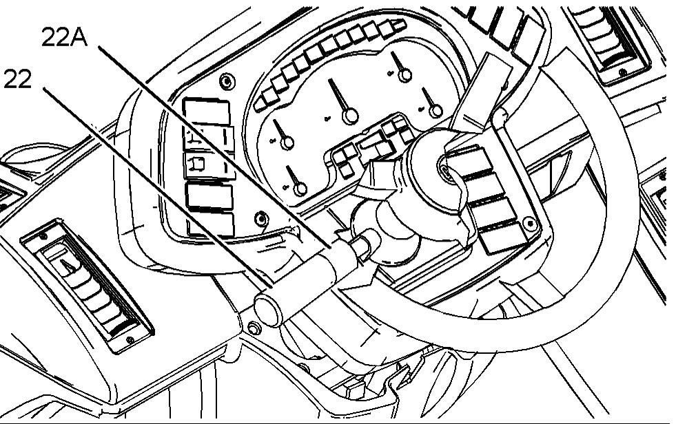
Illustration 75 g01147874
Four transmission speeds can be selected. The speeds are indicated on collar (22A). Rotate transmission control (22) until the required transmission speed is opposite the line. All four speeds can be selected for forward travel. Some machines are equipped with an automatic fifth speed. Machines that are equipped with this feature will automatically shift into fifth speed when the appropriate engine speed is reached. Fifth speed cannot be manually selected by the operator. The first three speeds can be selected for reverse travel. Select the proper speed for the application. Start moving the machine in first gear or in second gear. To upshift, move the transmission control to the next highest gear. It is not necessary to release the accelerator control. To downshift, move the transmission control to the next lowest gear. Do not skip gears when you down shift. Continue to shift through the gears in this way as the conditions are required. To prevent engine overspeed, do not downshift if the engine speed is high. Control the speed of the machine in order to suit conditions. Make an allowance for surface conditions, weather conditions and load. Note: The machine should be in first speed or second speed when you change the direction of the machine from forward to reverse or from reverse to forward. Select the correct gear before you travel downhill. Select the necessary travel speed before you start downhill. Do not change gears while you are going downhill. When you go downhill, use the same speed that would be used to go uphill. Do not allow the engine to overspeed when you go downhill. Use the service brake to prevent engine overspeed when you go downhill. Select a lower gear before you go down the same hill again. When you are travelling uphill, select a lower gear when the engine speed starts to fall. Drive the machine in the gear that will allow the required speed to be maintained. Do not allow the torque converter to slip and do not allow the engine to lug. Note: When you operate a machine on a slope, certain conditions may prevent the machine from changing to a lower gear. If the operator selects a lower gear and the current gear that is displayed next to the speedometer begins to flash, apply the service brakes. When the gear change has been completed, the gear display will cease to flash.
Manual Transmission
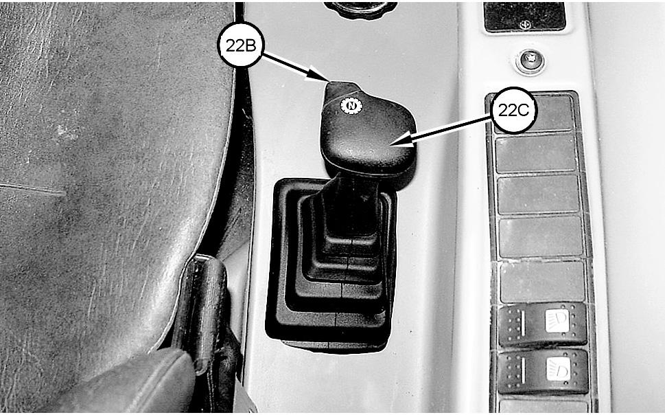
Illustration 76 g01147875
Some machines are equipped with a manual transmission shift.
Transmission Neutralizer Button (22B) -
Push the button and hold the button when you are changing speed ranges. This will disengage the transmission from the driving wheels.
Transmission Speed Shift Lever (22C) - Push transmission neutralizer button (22B) and hold button (22B) in order to neutralize the transmission. Then, move lever (22C) to one of the four desired travel speeds. All four speeds can be selected in both forward and reverse travel. Speed changes are possible when you are moving and when the machine is at full engine speed.

Illustration 77 g00846950
Directional Turn Signal Control (23)
Directional Turn Signal - Push up on switch (23) in order to activate the left turn signal. Pull down on switch (23) in order to activate the right turn signal. The mid-position is the OFF position.
Note: The turn signal only operates when the ignition is in the ON position.
Engine Start Switch (24)
Engine start switch (24) is located on the right side of the dash panel. The engine start switch has three positions. Electrical power is supplied to the systems in the cab when the engine start switch key has returned from the START position to the ON position.
OFF - When you insert the engine start switch key and when you remove the engine start switch key, the engine start switch key must be in the OFF position. To disconnect the power to the electrical circuits in the cab, turn the engine start switch key to the OFF position. Also, turn the engine start switch key to the OFF position in order to stop the engine.
When the key is in the OFF position the following circuits remain activated: • Hazard warning • Interior light • Parking lights
ON - Turn the engine start switch key clockwise to the ON position in order to activate all electrical circuits except the starting motor circuit. Before the engine will start, transmission control (22) must be in the NEUTRAL position. To start the engine, turn the engine start switch key clockwise from the ON position to the START position. Release engine start switch (24) after the engine starts. The engine start switch key will return to the ON position. Note: If the engine fails to start, return the engine start switch key to the OFF position. This must be done before you attempt to start the engine again. Note: As the machine powers up the machine goes through a number of self test and system checks. The machine is not available for operation for four seconds until the self test is completed. Your machine may be equipped with a security system. When a security system is installed, only the correct electronically programmed key will start the engine.
Steering Column Tilt Control (25)
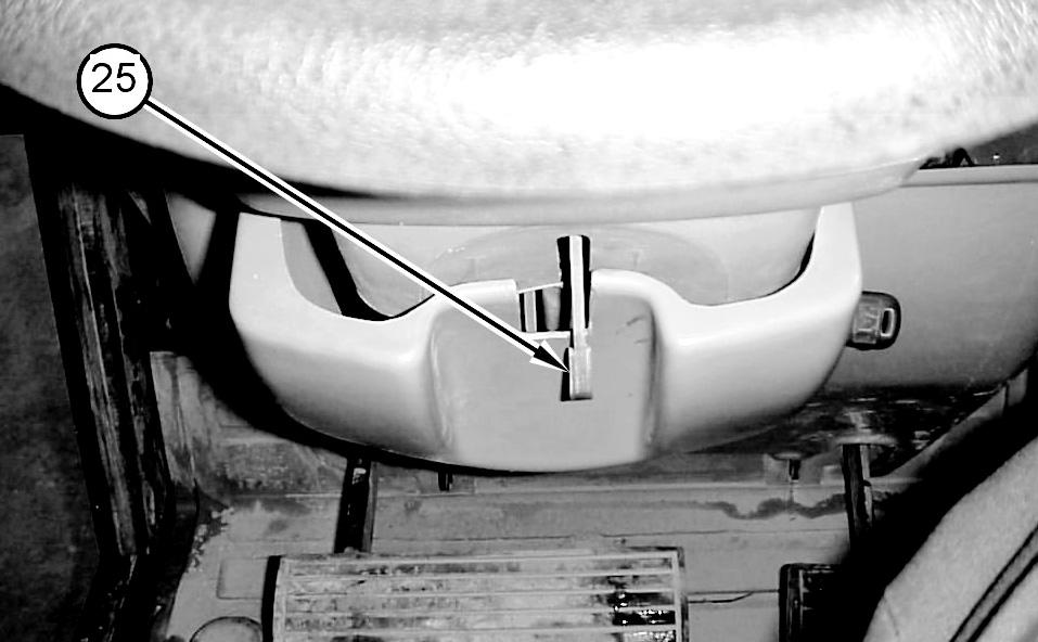
Illustration g01147877
If equipped, move lever (25) upward in order to unlock the steering column. Pivot the steering column to the desired position. Move lever (25) downward in order to lock the steering column in place. Always lock the steering column before you move the machine or before you operate the machine.
Machine Security System (If Equipped)
NOTICE This machine is equipped with a Caterpillar Machine Security System (MSS) and may not start under certain conditions. Read the following information and know your machine's settings. Your Caterpillar dealer can identify your machine settings.
Machine Security System (MSS) - Machines that are equipped with a Caterpillar Machine Security System (MSS) can be identified by a decal in the operator station. MSS is designed to prevent theft of the machine or unauthorized operation.
Basic Operation
MSS may be programmed to read a standard Caterpillar key or an electronic key. The electronic key contains an electronic chip within the plastic housing for the key. Each key emits a unique signal to the MSS. The keys can be identified by a gray housing or a yellow housing. MSS can have programmed settings to require an electronic key or a standard Caterpillar key for starting during certain periods of time. When the key start switch of the machine is turned to the ON position, the ECM will read the unique ID that is stored in the electronic key. The ECM will then compare this ID to the list of authorized keys. The
following table tells the operator the status for starting the machine. The status light is located near the key start switch.
Table 6
Green light Red light The machine will start.
The key is not authorized.
Note: MSS will not shut down the machine after the machine has started.
Security Management
The MSS has the capability to allow you to program the system to automatically activate at different time periods with different keys. The MSS can also be programmed to reject a specific electronic key after a selected date and time. When you turn the key to the OFF position and the MSS is active, you have a 30 second interval in order to restart the machine with an unauthorized key. Also if the machine stalls, there is a 30 second interval for restarting the machine. This 30 second interval is counted from the time of turning the key to the OFF position. Note: Know your machine's settings because the use of an electronic key is no guarantee that the machine can be restarted. An expiration date can be set for each electronic key that is contained in the list of keys for the machine. The key will no longer start the machine when the internal clock in the security system passes the expiration date. Each entry in the list of keys can have a different expiration date. Spare keys are available from your dealer. Before a key can operate the machine, the MSS must be set to accept that particular key. Consult your Caterpillar dealer for information on additional features of the MSS.