3 minute read
Dual relief valve manifold adjustment ........................... 5


Loop flushing valve adjustment
WARNING! Follow all standard safety procedures before beginning this adjustment process. Failure to do so may result in serious injury or death.
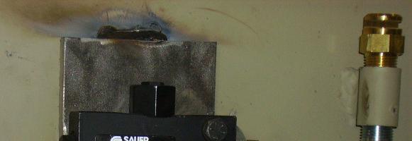
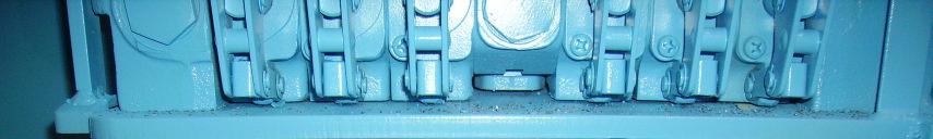
The loop flushing valve (Fig. 75) is mounted on the frame behind the breaker power unit. The valve is preset from the factory at 290 psi, which is measured by the charge pressure gauge while the conveyor is running.
If an adjustment is required:
Start the machine (see Start up procedure in this chapter).
Two people are required to adjust the pressure setting. One person must move the conveyor direction valve handle to the forward direction, relay pressure gauge readings to the mechanic making the adjustment, and be ready to shutdown the machine via the panic bar, if necessary.
WARNING! Two people are required to adjust the pressure setting. One person must move the conveyor direction valve handle to the forward direction and remain at the panic bar at all times during the adjustment procedure. Failure to do so may result in serious injury or death.
Operate the conveyor directional control lever to run the conveyor.
Loosen the jam nut on the adjustment hex by turning out (ccw).
Turn the adjustment hex in (cw) to increase the setting or turn out (ccw) to decrease the setting.
When the correct setting is obtained, tighten the jam nut on the adjustment stem by turning in (cw) while holding the adjustment hex in place.
N C . I C A , R I M E A R U S U C Y B ©
Fig. 75: Loop flushing valve
Loop flushing valve Jam nut and adjustment hex


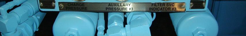

Charge pressure gauge
Dual relief manifold relief valve adjustments
WARNING! Follow all standard safety procedures before beginning this adjustment process. Failure to do so may result in serious injury or death.
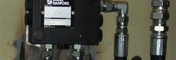
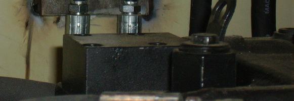
The dual relief manifold (Fig. 76) is mounted on the frame behind the breaker power unit. The purpose of the two relief valves is to limit the maximum pressure to each of the inlet sections on the primary valve bank. The design pressure setting is 2,250 psi. The setting for each relief is read from the corresponding auxiliary pressure gauge while deadheading a function. The top relief cartridge (2) limits the pressure into the first inlet section (both left sections and left tram) while the bottom relief cartridge (1) limits pressure to the mid-inlet section (right tram, tilt, and power fill).
To adjust relief cartridge 2:
Two people are required to adjust the pressure setting. One person must operate the lift cylinder valve handle on the primary valve bank, relay pressure gauge readings to the mechanic making the adjustment, and be ready to shutdown the machine via the panic bar, if necessary. The second person will perform the actual pressure adjustment at the dual relief manifold.
WARNING! Two people are required to adjust the pressure setting. One person must operate the lift cylinder valve handle and remain at the panic bar at all times during the adjustment procedure. Failure to do so may result in serious injury or death.
Measure the setting of cartridge 2 by fully extending or retracting (deadheading) one of the lift cylinders, then reading the pressure on
“AUXILIARY PRESSURE #2”gauge while the cylinder is deadheaded. The reading should be 2,250 psi.
WARNING! The feeder will move during this step and it must be ensured that all standard safety procedures are adhered to in order to avoid personnel injury and equipment damage. Do not operate the tram function during this adjustment procedure as it is unsafe. Failure to adhere to this warning may result in serious injury or death.
Loosen the jam nut on the relief by turning out (ccw).
Turn the hex key adjustment in (cw) to increase the setting or out (ccw) to decrease the setting.
Once the desired setting is obtained, tighten the jam nut by turning in (cw) while hold the hex key in place.
N C . I C A , R I M E A R U S U C Y B ©