8 minute read
Tailpiece steering cylinder............................................5


Tilt cylinder removal and installation
To remove a tilt cylinder (reference Fig. 101):
Shutdown the feeder breaker (see Shutdown procedure in this chapter).
Turn the circuit breaker to the “OFF”position and disconnect and lock and tag out the main power source. Follow all standard Federal and mine practices for locking/tagging out power sources.
WARNING! Before performing maintenance on the machine, the circuit breaker should be in the “OFF”position and power should be locked and tagged out at the main power source. Electrical shock or accidental machine movement can cause serious injury or death to personnel.
Disconnect, tag, and cap the hydraulic hoses going to the cylinder.
WARNING! Never disconnect a hydraulic hose if the circuit is pressurized or if there is a load on the circuit. If a hose is disconnected while the circuit is pressurized or a load is on it, the load will fall, causing damage to the machine or serious injury or death to personnel.
Attach an appropriate lifting device to the tilt cylinder.
WARNING! Serious injury or death can result from falling loads. Observe the safe working load limits of lifting devices and keep a safe distance from suspended loads.
Pull a cotter pin out of the pin through the cylinder eye and remove the pin.
Pull a cotter pin out of the pin through the rod eye and remove the pin.
To install a tilt cylinder (reference Fig. 101):
Attach an appropriate lifting device to the tilt cylinder.
WARNING! Serious injury or death can result from falling loads. Observe the safe working load limits of lifting devices and keep a safe distance from suspended loads.
Align the cylinder in the mounting clevises on the machine.
Install the pin through the cylinder eye and secure with a cotter pin.
Install the pin through the rod eye and secure with a cotter pin.
Reconnect the hydraulic hoses to the cylinder.
Reconnect power to the machine.
Purge the hydraulic system of air.
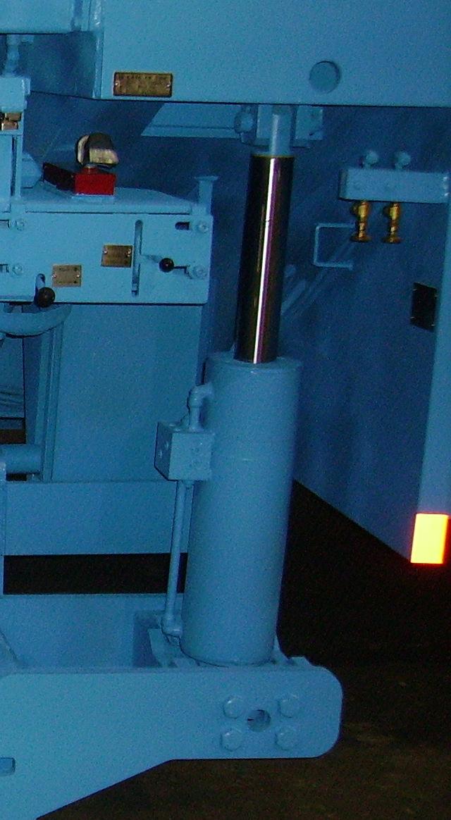
Fig. 101: Tilt cylinder removal and installation

Pin (2 places)
Cotter pin (4) (2 per pin)
Tilt cylinder (2)
N C . I C A , R I M E A R U S U C Y B ©
Lift cylinder removal and installation
To remove a lift cylinder (reference Fig. 102):
Shutdown the feeder breaker (see Shutdown procedure in this chapter).
Turn the circuit breaker to the “OFF”position and disconnect and lock and tag out the main power source. Follow all standard Federal and mine practices for locking/tagging out power sources.
WARNING! Before performing maintenance on the machine, the circuit breaker should be in the “OFF”position and power should be locked and tagged out at the main power source. Electrical shock or accidental machine movement can cause serious injury or death to personnel.
Disconnect, tag, and cap the hydraulic hoses going to the cylinder.
WARNING! Never disconnect a hydraulic hose if the circuit is pressurized or if there is a load on the circuit. If a hose is disconnected while the circuit is pressurized or a load is on it, the load will fall, causing damage to the machine or serious injury or death to personnel.
Attach an appropriate lifting device to the lift cylinder.
WARNING! Serious injury or death can result from falling loads. Observe the safe working load limits of lifting devices and keep a safe distance from suspended loads.
Pull a cotter pin out of the pin through the cylinder eye and remove the pin.
Pull a cotter pin out of the pin through the rod eye and remove the pin.
To install a lift cylinder (reference Fig. 102):
Attach an appropriate lifting device to the lift cylinder.
WARNING! Serious injury or death can result from falling loads. Observe the safe working load limits of lifting devices and keep a safe distance from suspended loads.
Align the cylinder in the mounting clevises on the machine.
Install the pin through the cylinder eye and secure with a cotter pin.
Install the pin through the rod eye and secure with a cotter pin.
Reconnect the hydraulic hoses to the cylinder.
Reconnect power to the machine.
Purge the hydraulic system of air.
Fig. 102: Lift cylinder removal and installation
Lift cylinder (2) Cotter pin (4) (2 per pin)
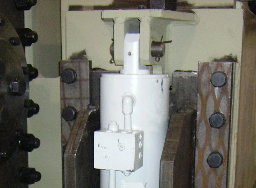
Pin (2 places)
N C . I C A , R I M E A R U S U C Y B ©
Tailpiece tilt cylinder removal and installation
To remove a tailpiece tilt cylinder (reference Fig. 103):
Shutdown the feeder breaker (see Shutdown procedure in this chapter).
Turn the circuit breaker to the “OFF”position and disconnect and lock and tag out the main power source. Follow all standard Federal and mine practices for locking/tagging out power sources.
WARNING! Before performing maintenance on the machine, the circuit breaker should be in the “OFF”position and power should be locked and tagged out at the main power source. Electrical shock or accidental machine movement can cause serious injury or death to personnel.
Disconnect, tag, and cap the hydraulic hoses going to the cylinder.
WARNING! Never disconnect a hydraulic hose if the circuit is pressurized or if there is a load on the circuit. If a hose is disconnected while the circuit is pressurized or a load is on it, the load will fall, causing damage to the machine or serious injury or death to personnel.
Attach an appropriate lifting device to the cylinder.
WARNING! Serious injury or death can result from falling loads. Observe the safe working load limits of lifting devices and keep a safe distance from suspended loads.
Pull cotter pin out of the pin through the cylinder eye.
Pull cotter pin out of the pin through the rod eye.
To install a tailpiece tilt cylinder (reference Fig. 103):
Attach an appropriate lifting device to the cylinder.
WARNING! Serious injury or death can result from falling loads. Observe the safe working load limits of lifting devices and keep a safe distance from suspended loads.
Align the cylinder in the mounting clevises on the machine.
Install the pin through the cylinder eye and secure with a cotter pin.
Install the pin through the rod eye and secure with a cotter pin.
Reconnect the hydraulic hoses to the cylinder.
Reconnect power to the machine.
Purge the hydraulic system of air.
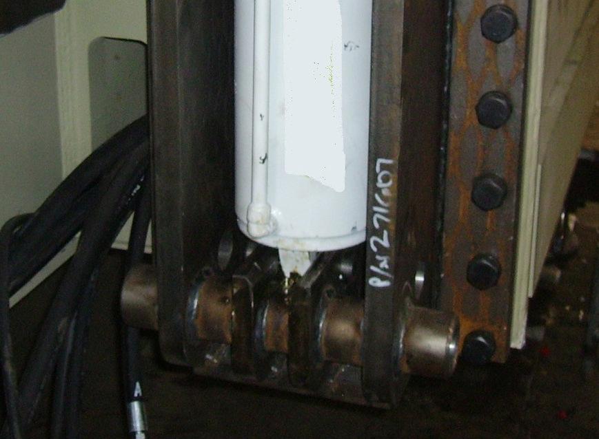
Fig. 103: Tailpiece tilt cylinder removal and installation
Cotter pin (4) (2 per eye)
Pin (2)
Tailpiece tilt cylinder
N C . I C A , R I M E A R U S U C Y B ©
To remove a tailpiece steering cylinder (reference Fig. 104):
Shutdown the feeder breaker (see Shutdown procedure in this chapter).
Turn the circuit breaker to the “OFF”position and disconnect and lock and tag out the main power source. Follow all standard Federal and mine practices for locking/tagging out power sources.
WARNING! Before performing maintenance on the machine, the circuit breaker should be in the “OFF”position and power should be locked and tagged out at the main power source. Electrical shock or accidental machine movement can cause serious injury or death to personnel.
Disconnect, tag, and cap the hydraulic hoses going to the cylinder.
WARNING! Never disconnect a hydraulic hose if the circuit is pressurized or if there is a load on the circuit. If a hose is disconnected while the circuit is pressurized or a load is on it, the load will fall, causing damage to the machine or serious injury or death to personnel.
Attach an appropriate lifting device to the cylinder.
WARNING! Serious injury or death can result from falling loads. Observe the safe working load limits of lifting devices and keep a safe distance from suspended loads.
Pull cotter pin out of the pin through the cylinder eye.
Pull cotter pin out of the pin through the rod eye.
To install a tailpiece steering cylinder (reference Fig. 104):
Attach an appropriate lifting device to the cylinder.
WARNING! Serious injury or death can result from falling loads. Observe the safe working load limits of lifting devices and keep a safe distance from suspended loads.
Align the cylinder in the mounting clevises on the machine.
Install the pin through the cylinder eye and secure with a cotter pin.
Install the pin through the rod eye and secure with a cotter pin.
Reconnect the hydraulic hoses to the cylinder.
Reconnect power to the machine.
Purge the hydraulic system of air.
Fig. 104: Tailpiece steering cylinder removal and installation
Pin (2)
Tailpiece steering cylinder Cotter pin (4) (2 per eye)
N C . I C A , R I M E A R U S U C Y B ©