2 minute read
Crawler track adjustment ..............................................5


Instructions on the adjustment procedures
The purpose of this section is to provide procedures for the major adjustments required on the feeder breaker.
It is essential that adjustments be made periodically to the conveyor chain and crawler tracks, as otherwise damage can be caused to other parts of the machine or to the assembly itself. Inspect the adjustments at regular intervals.
In addition to the mechanical adjustments, there are hydraulic settings and electrical timers that may require adjustment.
Conveyor chain adjustment
The conveyor chain is a complete assembly and should be checked for correct tension at regular intervals.
NOTICE! The following adjustment procedure for conveyor chain take-up must be performed on both right and left hand sides of the conveyor.
To adjust tension on the conveyor chain with the take-up cylinders proceed as follows (Fig. 70):
Close the needle valve on manifold assembly securely.
Attach a grease gun to the grease fitting located on the manifold and apply grease until the required pressure is attained. Sight across the bottom of the head shaft sprocket. The chain should sag 1 1/2”to 2”below the bottom of the head shaft sprocket.
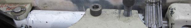
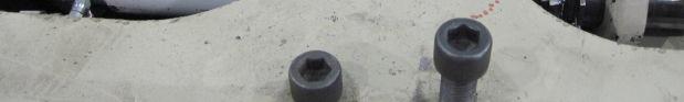
After tensioning chain, remove the allen head bolts from the tail shaft retainers and lift out retainers.
Insert shims over cylinder rod to maintain gap between bearing and end plate of box. Measure the exposed rod length on the grease take-up cylinders and make sure they are within 1/4”of each other.
NOTICE! Make certain that the same amounts of shims are used on both sides of the conveyor to prevent chain from stretching unevenly. Incorrect tension or adjustment can cause premature wear of sprockets and chain. Measure the exposed rod length on the grease take-up cylinders and make sure they are within 1/4”of each other.
Allow tail shaft pressure to rest completely on shims.
Replace retainers.
Release pressure on the take-up cylinders by opening the top valve to vent grease. After grease has vented, close valve.
WARNING! Due to grease cylinders being under high pressure, do not stand in direct line of grease fitting or needle valve when releasing pressure. You could be seriously injured from high pressure grease.
Store any unused shims under cover plate.
Fig. 70: Conveyor chain adjustment


Shims Shim storage
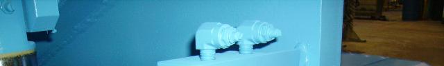


Needle valve (2)
Grease fitting (2)
N C . I C A , R I M E A R U S U C Y B ©