6 minute read
Internal Outputs


The number ZERO 0 means that this PCT is NOT driving this output true now, but, this output is programmed to be TRUE at another time.
A HYPHEN - means that this PCT is NOT programmed to activate this output.
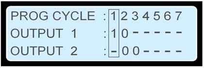
FIGURE 46: PCT DISPLAY EXAMPLE
PCT #1 is ACTIVE, 1 -- Output #1. Output #2 is NEVER enabled (the ‘-‘ in the bottom row). PCT #2 is NOT active, 0 -- however, when it is active, it activates both Output #1 and Output #2. The two zeroes show that this PCT will ENABLE both outputs when it becomes active. PCT #3 is NOT active. When it becomes active it will ONLY activate Output #2. PCT #4, PCT #5, PCT #6, and PCT #7 are DISABLED. They NEVER activate Output #1 or Output #2. SETPOINTS associated with Programmable Cycle Timer are configured from this screen by scrolling LEFT and RIGHT until the desired PCT is within the selection box and then pressing the ENTER KEY .
INTERNAL OUTPUTS
The PCT has two internal outputs; these should not be confused with the physical outputs of the control. The outputs are connected to internal logic. In the standard logic configuration, PCT Output #1 is connected to a REMOTE INITIATE command and PCT Output #2 is connected via Digital Selector #6 to Relay Output #8. This effectively allows the operator to configure a timed relay, for external connectivity. The status of the PCTs can be found within the menu structure at Control -> Prog Cycle Timer, an example is shown in FIGURE 47. The seven times are displayed across the top row. For the Output 1 and Output 2 rows, the number one 1 means that this Programmable Cycle Timer is driving that output to be true. The number zero 0 means that this Programmable Cycle Timer is not driving this output true but, that it would at other times. A hyphen - means that this Programmable Cycle Timer never activates this output.
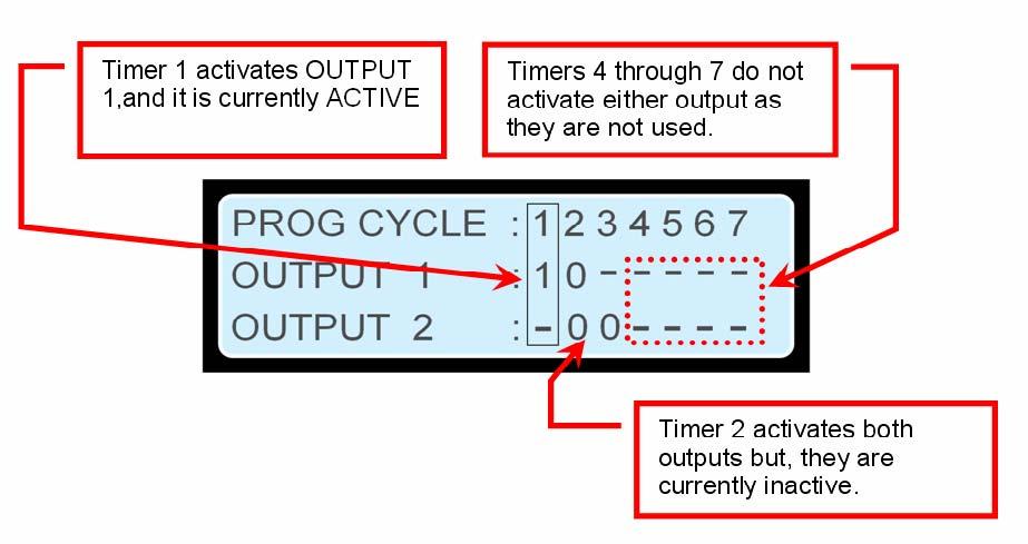
FIGURE 47: PROGRAMMABLE CYCLE TIMER STATUS SCREEN
The setpoints associated with Programmable Cycle Timer are configured from this screen by scrolling left and right until the desired Programmable Cycle Timer is within the selection box and then pressing ENTER KEY .
14 REDUCED POWER MODE
REDUCED POWER MODE (RPM) is a feature that puts the control into a state where the power consumption is reduced. RPM is intended to extend the amount of time the generator can sit between runs before the control drains the batteries too low to crank the generator in cases where a battery trickle charger is not fitted. In order to reduce the power consumed when in RPM, many functions within the control are turned OFF.
TURNED OFF DURING RPM
The display The communication lines Most inputs All outputs LEDs (lamps) on the front of the control blink briefly every second (rather than being on continuously). When RPM is enabled, the control will only enter RPM after a programmable time delay provided the generator is stopped and no keys have been pressed during the delay time. The control will wake from RPM on any one of the following conditions:
WAKE FROM RPM
Input 1 (Emergency-Stop) is grounded Input 2 (Remote Initiate) is grounded A key on the keypad is pressed The Programmable Cycle Timer is about to enter a period when it will activate an output.
CAUTION: Cat generator sets normally use an active high contact of E-Stop to the control. When there is no E-Stop, input 1 (E-Stop) is normally in the grounded state. This is one of the conditions to leave RPM or the control would never enter RPM. Therefore, in order to make use of Reduced Power Mode on a Cat genset, the customer/dealer needs to be aware that they are giving up the fail-safe nature of E-Stop and they have to rewire any E-Stop contacts connected to the control.
NOTE: In many cases there is a redundant fail-safe contact of the E-Stop switch controlling the fuel or connected to the Engine ECU on electronic engines)
ACTIONS TO ENABLE RPM
1. Ensure all the contacts of Emergency-Stop that are wired to the EMCP3 are normally open (Normally Open switch). This will cause an E-Stop event, this resolved in the next step.
2. Set the active state of Digital Input #1 to active low. Reset the E-Stop event. 3. Change the setpoint Reduced Power Mode Enable Status to ENABLED. This can be done with either ET or using a level 3 password to navigate Configure -> Setpoints ->
Other -> Reduced Power Mode. 4. The setpoint Reduced Power Mode Delay Time should be checked. It should be at a desirable value. This value is the amount of time (once the generator is at rest and after the last key-press) before the control will go into Reduced Power Mode.
Semi-Awake The EMCP 3 becomes SEMI-AWAKE when in Reduced Power Mode. Approximately every 30 minutes it well do status checks of the control for about 40 seconds. The control checks the status of the resistive senders, Magnetic Pick-Up, raise any SHORTED or OPEN events (if detected), and will activate any relays (such as common alarm). During SEMI-AWAKE the display remains off and the LEDs (lamps) continue to blink. Once the SEMI-AWAKE time is completed the control will return to full RPM (deactivating any relays that are active).
15 PROGRAMMABLE TRIP POINT FUNCTION
The standard configuration on EMCP 3.2 and 3.3 has one Programmable Trip Point function block configured to respond to the %KW of the genset (this feature is not available on EMCP 3.1. It is not capable power monitoring).
NOTE: The Programmable Trip Point function cannot be configured to act upon a different parameter from %KW. In order to obtain such a capability, a custom flash file must be ordered. Contact your Caterpillar dealer for details.
The setpoints of this block are configured by default such that, if the %KW exceeds 90% for 10 seconds then the output of the block will become true and remain true until the %KW drops below 85% for 1 second. The output of the Programmable Trip Point function block can be configured through Digital Selector #2 to Relay output #4 or through Digital Selector 7 to Digital (transistor) Output #1. The setpoints in the Programmable Trip Point function can be changed from the display, they are as follows:
PROGRAMMABLE TRIP POINT FUNCTION TRIGGER CONDITION
[Default = Trip Above Threshold] This selects whether the output will be active if the value is above or below the threshold.
PROGRAMMABLE TRIP POINT FUNCTION PERCENTAGE THRESHOLD
[Default = 90%] This is the threshold that the measured parameter must pass to change the state of the output, in the default case (%KW) this is 90% of rated kW.
PROGRAMMABLE TRIP POINT FUNCTION HYSTERESIS PERCENTAGE
[Default = 5%] Once the output is on, the value must return by thus much past the Threshold before the output turns off again, in the default case (%KW) this 5% causes the relay to not turn off again until 85% of rated kW (90-5). This hysteresis is used to ensure that a value close to the threshold does not cause the output to rattle on and off.
PROGRAMMABLE TRIP POINT FUNCTION TRIP ACTIVATION DELAY TIME
[Default = 10 seconds] This is the time that the value must exceed the threshold before the output of the block becomes active. It is used to ensure that the momentary transients are ignored.
PROGRAMMABLE TRIP POINT FUNCTION TRIP DEACTIVATION DELAY TIME
[Default = 1 seconds] This is the time that the value must return past the threshold before the output of the block becomes inactive again. It is used to ensure that the momentary transients are ignored.


