1 minute read
Thermocouple Features


Since the FMI codes are implied by this column, the FMI column is grayed out for any of these selections. The only option that will allow an FMI to be configured is SPECIFIC DIAGNOSTIC.
SUSPECT PARAMETER NUMBER
The Suspect Parameter Number column is used to select or type in the SPN for the parameter assigned to the LED pair. Most supported SPNs can be selected from the list. Refer to the SAE J1939 literature or RENR7902 Systems Operation Testing and Adjusting Manual for a complete list of supported SPNs.
NOTE: Remember to click the Submit button at the bottom of the LED Pair Configuration tool after making the selections for each LED pair. Only then will the new settings take effect. If you make selections and attempt to leave the LED Pair Configuration tool, a prompt will ask you if you wish to have your changes take effect. If you decline, your changes will be lost.
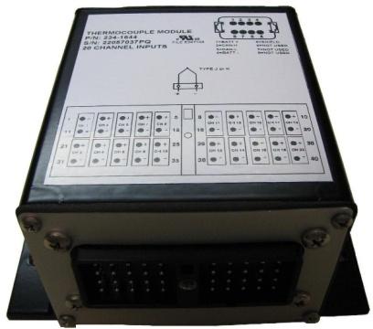
17.2 THERMOCOUPLE MODULE (EMCP 3.3)
THERMOCOUPLE FEATURES
Reads up to 20 Type J or K thermocouple inputs Temperatures are configured to indicate the SAE J1939 SPN to be transmitted by that temperature input. Suspect Parameter Numbers (SPNs) for configuration of temperature inputs are customer specific. Resolution: One byte parameters have a resolution of 1 °C / bit and a range of -40 °C to 210 °C. Two byte parameters have resolution of 0.03125 °C / bit and a range of -273 °C to 1735 °C Cold junction compensation is provided System throughput has all 20 channels scanned in 2 seconds (100 ms/channel) Overall drift with temperature is 0.015% / °C of span (maximum) Module is fully functional during configuration and communications Parameter values and diagnostic error codes are retained when the modules are deenergized Open-circuit and short-circuit diagnostics are supported Can be mounted directly on the generator set panel or remotely Suitable for moist, high shock and vibration environments Compact size (see mechanical drawing, FIGURE 55)


