2 minute read
Figure 14: Caterpillar Service Tool l Annunciator LED Configuration Screen


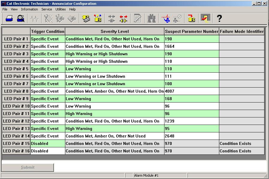
Figure 14: Caterpillar® Service Tool Annunciator LED Configuration Screen
Each LED pair has four parameters required to configure it. It is best to configure the four columns in order from left to right; first Trigger Condition, next Severity Level, then Suspect Parameter Number, and finally Failure Mode Identifier (if required). The reason for the order is because the value set in one column affects the choices available in the subsequent columns. If a field is grayed out, it is not available due to conditions set in previous columns.
Trigger Condition: There are three possible selections for Trigger Condition; Specific Event, General Event, and Disabled.
Specific Event is used to assign an LED pair to a specific data link parameter, such as Oil Pressure, Engine Speed, Coolant Temperature, etc.
“General Event” is used to assign an LED pair as a general alarm or shutdown indicator. When configured as General Event, the LED will not be assigned to a particular parameter. It will respond to any event, regardless of the Suspect Parameter Number. For this reason, when General Event is selected, the Suspect Parameter Number cannot be changed.
Disabled is used to disable the LED pair. The remaining three parameters will be grayed out when Disabled is selected.
Severity Level: Severity Level defines how the LED pair will react to various levels of event conditions. Selections that begin with “Condition Exists” will respond to J1939 Event messages for FMI 31 “Condition Present”. For example, LED pair #2 is
configured for “Condition Exists, Red On, Other Not Used, Horn On” with SPN 190 (Emergency Stop Active). This means that when the Annunciator received a J1939 message indicating Emergency Stop with FMI 31, the Red LED will turn on and the Horn will also turn on. “Other Not Used” indicates that the other LED color in the pair is never used. “Green Off” indicates that the green LED (for example) lights when the condition chosen for this LED pair is NOT active.
The Severity Level selections imply a J1939 Failure Mode Identifier (FMI) code. “Condition Exists” is equivalent to FMI 31. High Warning can be FMI 15 or FMI 16. Low Warning can be FMI 17 or FMI 18. High Shutdown is equivalent to FMI 0. Low Shutdown is equivalent to FMI 1. The FMI column is grayed out for any of these selections. The only option that will allow an FMI to be configured is “Specific Diagnostic Code”.
Suspect Parameter Number: The SPN column is used to type in the Suspect Parameter Number for the parameter assigned to the LED pair. Refer to the SAE J1939 literature or the EMCP 3 Systems Operation Testing and Adjusting Manual RENR7902 for a complete list of supported SPNs.
NOTE: Remember to click the Submit button at the bottom of the LED Pair Configuration screen after making the selections for each LED pair. Only then will the new settings take effect.

