1 minute read
5.3.2 Control Circuit and Auxiliary Voltage Connections

from Cat Electric Rope Shovel 295HD/ HR Drive Converter Cabinet Bucyrus Shovel Operation & Maintenance Ma

5.3.2 Control Circuit and Auxiliary Voltage Connections
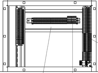
The control connection terminals are located at the bottom of the cabinet in the PLC compartment as shown below Fig. 5-7. The terminals are used to connect various control connections of Shovel electrics to PLC & power cabinet. Refer latest version of terminal diagram document number 4W-2601-1644714 and circuit diagram for details.
MTB2
LTB1 HTB5 MTB1 X69
X70
HTB1 HTB2
HTB6
GROUND CONECTION
Fig. 5-7 Control connections located at the bottom of PLC compartment
Siemens Ltd. A5E01511750J/ 4M-2601-1645240 AC Shovel 295HD/ HR DCC Operation & Maintenance Manual 69
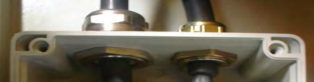

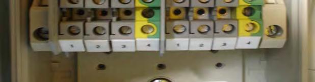
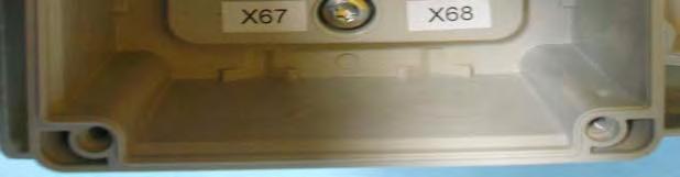
Fig. 5-8 Terminal box to connect power supply to blower & pump
Use terminal X68 to connect supply voltage to centrifugal pump and terminal X67 to connect supply to main blower as shown in Fig. 5-8
For Profibus & Ethernet connections, use rubber grommets provided in the PLC compartment. Out of these two connections one is to be used for connecting Profibus node and the other for connecting Ethernet cable coming from JLT operator panel display.
Siemens Ltd. A5E01511750J/ 4M-2601-1645240 AC Shovel 295HD/ HR DCC Operation & Maintenance Manual 70


