3 minute read
7.3.3 Replacing

from Cat Electric Rope Shovel 295HD/ HR Drive Converter Cabinet Bucyrus Shovel Operation & Maintenance Ma

7.3.3 Replacing
Removing
• Remove power cable connection from output side busbar cable no. 11004(1x), 11005(1x), 11006(1x), 11110(2x), 11111(2x), 11112(2x), 11103(1x), 11102(1x), 11101(1x), 11108(1x), 11107(1x), 11109(1x) by unscrewing Hex nut M12, plain, spring washer (pos 616, 613, 612) using 18 no. bit & torque wrench. • Remove power cable connection from input side busbar cable no. 10901(1x), 10902(1x), 10903(1x), 10701(1x), 10702(1x), 10703(1x) by unscrewing hex nut M12, plain, spring washer (pos 616, 613, 612) using 18 no. bit & torque wrench. • Remove all electrical connections of motor module from shield bracket by unscrewing 4mm clamp (pos 692), Torx screw M3*89 (pos 648) using kombi screw driver. • Remove switch module (pos 180) one by one by unscrewing hex screw M10, plain, spring washer (pos 631, 629, 630) using 16 no. bit & torque wrench. • Remove motor module (pos 170) by unscrewing hex screw M10, plain, spring washer (pos 625, 629, 630) using 16 no. bit & torque wrench. • Remove mounting bracket from cabinet by unscrewing hex screw M10, plain, spring washer (pos 631, 629, 630) using 16 no. bit & torque wrench.
Installing
• Assembly of Switch module to be done outside of the panel • Take switch module, place it on table, Mount Busbar (Top rear-pos 26, Top front-pos 25, bottom rear-pos 29) (18x) on three modules by screwing Hex screw 3/8 " 16 UNC,plain,spring washer (pos 633, 629, 630) using 13 no bit & torque wrench. • Apply torque 15 Nm, Mark torque points with marker pen. • Mount bracket (pos 20) on cabinet by screwing hex screw M10, plain, spring washer (pos 625, 629, 630) using 16 no bit & torque wrench. • Apply torque 50 Nm, mark torque points with marker pen. • Mount motor module (pos 170) on bracket by screwing Hex screw M10, plain, spring washer (pos 625,629,630) using 16 no bit & torque wrench. • Apply torque 50 Nm, mark torque points with marker pen. • Mount three switch module(pos 180) one by one on bracket by screwing hex screw M10, plain, spring washer (pos 631,629,630) using 16 no bit & torque wrench. • Apply torque 50 Nm, mark torque points with marker pen. • Mount power cable connection to output side busbar (Top rear-pos 26, Top front pos-25) cable no.11004(1x), 11005(1x), 11006(1x), 11110(2x), 11111(2x), 11112(2x), 11103(1x), 11102(1x), 11101(1x), 11107(1x), 11108(1x), 11109(1x) by screwing Hex screw M12*35 (pos.620,for single connection), Hex screw M12*45 (pos 615 for double connection) , hex nut M12,plain,spring washer (pos 616, 613, 612) using 18 no bit & torque wrench. • Also mount power cable connection to input side busbar (Bottom rear pos,29) cable no, 10901(1x), 10902(1x), 10903(1x), 10701(1x), 10702(1x), 10703(1x) by screwing Hex screw M12*35 (pos.620, for single connection), hex screw M12*45 (pos 615 for double connection), hex nut M12,plain,spring washer (pos,616,613,612) using 18 no bit & torque wrench. • Apply torque 50 Nm, mark torque points with marker pen.
Siemens Ltd. A5E01511750J/ 4M-2601-1645240 AC Shovel 295HD/ HR DCC Operation & Maintenance Manual 97
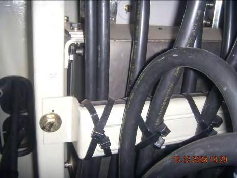
• Tie all power cable to tie rod using cable ties & tie gun. • Make all electrical connections of motor module with shield bracket using screwing 4mm clamp (pos, 692), Torx screw M3*89(pos, 648) using kombi screw driver.
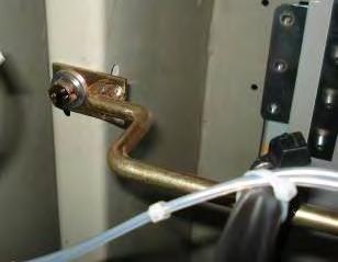
Mounting of cable tie rod
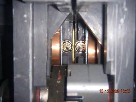
Bus bar
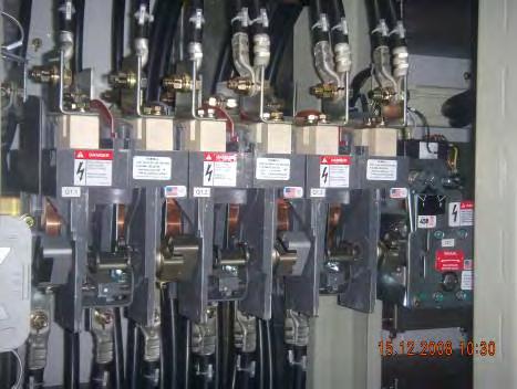
Switch Module Power cable connections
Cable tie rod
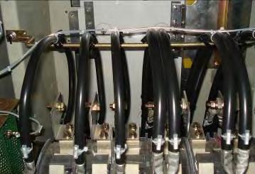
Electrical connections of motor module
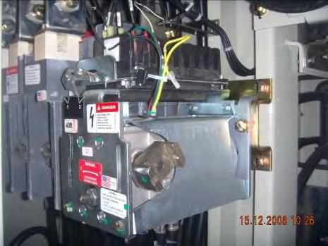
Mounting of Switch Module Motor Module
Siemens Ltd. A5E01511750J/ 4M-2601-1645240 AC Shovel 295HD/ HR DCC Operation & Maintenance Manual 98


