40 minute read
Operator’s Seat and Controls


Operator’s Seat and Controls
As the first walking step commences and the shoes move off their PARK position, the swing and hoist brakes will automatically set if they had not already been set manually. During extended travel over long distances, it sometimes becomes necessary to alter the direction of travel or position the bucket. This can be done without transferring to the DIG mode. Stop the walking shoes in the PARK position. Check that the SWING CONTROL indicator is lit and the propel brakes are set. Press the EXCITATION ON pushbutton, and then release the Swing brakes. Reposition the dragline to the desired direction of travel. To continue propelling, press the EXCITATION ON pushbutton and release the propel brakes.
During walking, if a ground roll develops at the front edge of the tub, “heel” the bucket for a couple of steps. If the tub roll persists, swing the machine 30º - 40º to one side and propel one or two steps. This will spread the roll over the ground. Then return to the line of travel desired.
When the machine is walking, both shoes should contact the ground at the same time. If one of the shoes sets down on a high spot, or does not contact the ground, or steps into a soft ground area that will not support it, then the machine will rotate in relation to the tub if the walking step is completed. If this occurs and the operator can, he should stop the step before the machine is lifted and reverse the shoes up to top dead center position. He can then change machine travel direction with the swing motion and walk around the problem ground area.
When the number of steps taken is completed and return to digging is required, the operator can press “SHOE AUTO PARK” in the second half of the last step. Keeping the joystick rearward, the machine will complete the step and slow the shoes as they approach their park position. The propel brakes will set when each shoe has reached its park position.
TURNING THE MACHINE
Conduct the following operation to turn the dragline.
1. Press the Auto Park button to the left of the left joystick controller, while continuing to hold the Propel Joystick back in the walking travel direction to bring both shoes up into an auto park position.
2. Move the drag/propel joystick to the neutral position.
3. Set the propel brakes.
4. Sound the horn twice to indicate movement.
5. Release the swing brake.
6. Swing the boom to the correct position and return the swing controllers to neutral.
7. Set the swing brakes.
8. Sound the horn three times to indicate propel movement.
9. Release the propel brakes.
10. Pull back on the joystick to lower the shoes for walking the dragline.
RETURNING TO DRAG (DIGGING) MODE
The machine will need to be returned to drag mode to begin digging after the machine has been repositioned.
1. With the shoes parked, move the propel controller to neutral.
2. Set the propel brakes.
3. Press the Excitation Stop button on the right console to stop excitation.
4. Transfer from propel to drag mode by pressing the Propel button on the right console.
5. Sound the horn twice to indicate movement.
6. To start excitation, press the Excitation Start button on the right console.
7. Release the hoist, drag, and swing brakes.
8. The machine is ready to start digging.
NORMAL SHUTDOWN PROCEDURE
To shutdown the machine:
1. Place the bucket on the ground.
2. Set all brakes.
3. Press the Excitation Stop pushbutton.
This process first slows the Drag/Propel motor speed, then sets the mechanical brakes and turns off the generator/motor field drive.
PARK AND SHUTDOWN PROCEDURE
Park the machine in a safe position, away from the low wall edge, on firm level ground. If the machine is currently in propel mode, transfer to drag mode. The machine must be in drag mode to shut the machine down properly and set the bucket on the ground.
The shutdown procedure first involves shutting down the functions in the operator cab, then the power in the machinery house.
Operator Cab Shutdown Sequence
1. Set the bucket on the ground in a safe location with all of the controllers in neutral.
2. Set the hoist, drag, and swing brakes.
3. Press the Excitation Stop button on the right console to stop excitation.
4. Shut down the MG set on the right console.
5. Move to the house power control center control panel.
Machinery House Shutdown Sequence
1. Shut down the blowers.
2. Shut down the fans.
3. Shut down the oil and cooling pumps.
4. Call for an electrician to shut down the power sources.
EMERGENCY SHUTDOWN PROCEDURE
1. Press the E-Stop pushbutton on the right console. This will cause an immediate shutdown of the entire machine. All drive motions will stop, all mechanical brakes will set and the generator/ motor field drives will turn off.
2. Follow standard mine procedures and/or notify mine personnel as to the reason the machine was shut down.
TIGHTLINE PARAMETERS
The Bucyrus Tightline Control System reduces motion reference values whenever hoist and drag operation occurs within a preset envelope. All of the control algorithms are done in the PLC and all setup parameters are entered using the operator’s interface terminal. The system uses hoist and drag rope lengths and velocities obtained from encoders coupled to the drums. The encoder calibration, motion slowdown, and stop limit logic is independent of the tightline control. One encoder per motion is used to provide the position information for both tightline and limits.
The PLC continuously calculates the hoist and drag rope lengths and velocities from the drum encoder signals. The hoist and drag chain/hardware lengths are summed with the calculated rope lengths to determine the operating envelope. The rope velocities are positive for the hoist and drag directions. These are summed algebraically to give a net rope velocity. If this velocity is positive, it is multiplied by the rope velocity factor to form a dynamic compensation length. This is then added to the dynamic tightline length parameter. Whenever the operating envelope is less than the dynamic tightline length with velocity compensation, the motion reference or references causing the tightline condition will be reduced. If the operating envelope continues to decrease, the references will be reduced to zero when the static tightline length is reached.
The tightline protection must operate rapidly to stop the motion. The system changes the reference ramps to allow faster motion response. If the bucket enters the static tightline envelope by a small amount, the brakes will be set and the motions turned off. To exit the tightline condition, the appropriate motion must be moved away from the Boom. The Tightline Final Limit must be exited with the Limit Bypass Mode. When the machine is in a hoist or drag limit, the tightline operation is suspended for the motion in limit.
The final limit can be exited from within the rope limit bypass mode.
The rope limit bypass mode is entered by pressing and holding the bypass button in the cab. The rope bypass light will flash. The motion can be started by control start, once the motion control-on light is lit and the bypass mode is latched. The rope bypass light will be on. The motion brakes can then be released and the motion moved out of the final limit. If the motion is moved in the wrong direction, rope limit bypass mode will be exited and the motion will shut down. Speed is limited to 15% in bypass mode. When the motion is outside the static tightline envelope, rope limit bypass mode will be exited. Normal tightline limit functions will be active.
Dynamic tightline velocity compensation provides anticipation at higher operating speeds by increasing the dynamic tightline length and thereby reducing motion reference earlier than at lower operating speeds.
The theoretical tightline length is the straight-line distance between the drag rope exit point at the fairlead sheaves to the hoist rope exit point at the boom point sheaves. This length is somewhat smaller than the dragline boom length. The following are conservative values for static and dynamic tightline lengths:
• Static tightline length = 1.10 x theoretical tightline length
• Dynamic tightline length = 1.16 x theoretical tightline length
Refer to the machine settings for actual values.
The hoist and drag encoders need to be calibrated prior to tightline set up. This is a separate procedure.
The tightline protection requires information to be entered on the operator display to set the tightline limits. This is a password protected screen.
• Static tightline length = Hoist and drag envelope for zero reference.
• Dynamic tightline length = Hoist and drag envelope where reference reduction starts.
• Hoist chain/hardware length = Chain and hardware lengths from the hoist rope socket to the bucket hoist trunnion.
• Drag chain/hardware length = Chain, hardware, and bucket lengths from the drag rope socket to the bucket hoist trunnion.
• Rope velocity factor = Dynamic tightline length velocity compensation.
The data entry can be selected in meters or feet. The PLC calculates in meters. The Chain Hardware lengths are shown in the attached figure.
The hoist chain/hardware length and Drag chain hardware length should be physically measured prior to the operation of the dragline and should be measured on site; these measurements should be recorded for later use. These measurements will be required to be input into the tightline parameter screen in the operator’s cab OIT.
The tightline protection can be turned off with the rope limit bypass pushbutton. This will enunciate a visual tightline protection off fault. The time that tightline protection is turned off will be recorded by the PLC.
JOYSTICK CALIBRATION
The Hall Effect type Joystick is designed for use on mining equipment with the output voltage for the x and y axis between +/- 10 volts dc and zero volts in the neutral (center) position. The Joystick will have spring return in both the x axis and y axis with a full throw handle travel of 30 degrees off neutral for each axis. The Joystick will include a “type GK2” pushbutton incorporated in the handle with a change over contact.
Each Joystick provides an analog signal to the PLC for each axis of motion and is interpreted as the operator’s control request for each respective motion. There are also discrete signals that are used in conjunction with the analog signal to determine the operator’s request.
The Joystick calibration takes the raw data input and creates a scaled value in the PLC equal to +/ - 10 volts. This can compensate for drift in the input signals.
There are conditions that are checked for in the software including Joystick neutral readings and power supply checks. If an out-of-tolerance condition is detected, a fault is posted on the Operator Display.
NOTE: The Joysticks are the same for all the motions (dual axis). Therefore, in the Drag Joystick, the Y-axis is not used and labeled as a spare.
REMOTE ROPE REEVING
Rope Reeving (Drum Inching Control) is used by maintenance in the installation or removal of the hoist or drag wire ropes, and for drum maintenance. Rope Reeving is controlled by the Pony Drive System.
The Pony Drive system is comprised of one (1) electric motor directly coupled to a hydraulic pump. The pump flow is controlled by two (2) proportional directional control valves. Each valve is used to control a separate hydraulic motor, one for hoist and one for drag. The system is designed to “ramp in or ramp out” providing a controlled speed change. It is a single speed bi-directional system.
The MC-1000 Radio Control Pendant will have the following controls:
Function Buttons:
F0: Brake Release
F1: Brake Set
F2: Forward
F3: Reverse
F4: Pump Start F5: System Enable F6: Pump Stop
The DC Drives, MG Sets and bleed fans must be off when Reeving mode is selected.
CAUTION: ROPE AND TIGHTLINE LIMITS ARE TURNED OFF WHILE IN REEVING MODE, OTHER NORMAL PROTECTIONS ARE STILL ACTIVE. WHEN ALL REQUIREMENTS ARE MET THE PLC WILL SEND A SIGNAL THAT ALLOWS THE PONY DRIVE SYSTEM TO BE TURNED ON.
The pony drive system is activated by pressing the hydraulic motor start button located on the pendant.
The hydraulic motor for hoist or drag is manually engaged by sliding the unit into the hoist or drag drum input shaft. Each hydraulic motor is mounted on a sliding frame adjacent to the Hoist and Drag drums. While sliding the hydraulic motor in place, the operator can use the controls to jog the hydraulic motor to line up with the drum for engagement. A proximity sensor will sense when the hydraulic motor of the pony drive is fully engaged in the drum. The PLC will then enable the brake release pushbutton.
Rope Reeving is conducted from the machinery house with the MC-1000 Radio Control Pendant. A pushbutton is pressed to cause CW or CCW motion; the selected motion will continue as long as the pushbutton is pressed, releasing the pushbutton will cause the drive to stop. Only one pushbutton will respond if more than one is pressed, the first button pressed will have priority.
The Pony Drive system has two faults that will shut it down and set brakes, neither of these will be enunciated to the PLC. Low oil level is triggered if the oil level in the hydraulic power pack falls below a preset level. High oil temperature is triggered when the oil temperature in the hydraulic power pack reaches a preset temperature.
If a communication fault occurs between the local control panel and the pendant, the pony drive will stop and the brakes will set. Once communication has been reestablished, it will be necessary to restart the pony drive system.
The PLC will set the brakes when the hydraulic motor is stopped or the proximity switch indicates that the pony drive hydraulic motor is not fully engaged. Anytime the head is neither fully engaged nor fully disengaged, the brakes will be set. A proximity switch will sense when the head is fully disengaged indicating to the PLC that normal machine operation will be allowed to commence. All applicable starting procedures will be followed.
If either of the hydraulic motors moves from fully disengaged while the MG sets are running, a fault will be initiated and hoist or drag will be immediately shutdown.
DANGER: THE NATURE OF THIS PROCEDURE ALLOWS PERSONNEL TO BE IN CLOSE PROXIMITY TO THE ROPES AND DRUMS WHILE THEY ARE IN MOTION. ALL RELEVANT SAFETY PROCEDURES MUST BE FOLLOWED.
AIR SYSTEM
The machine requires a compressed air system to provide for the release of the motion brakes and the lubrication system.
There are two air compressors on board the machine. These are standalone units with their own protective and operational controls.
The machine PLC monitors the on/off status and health of each compressor.
Additionally there is a pressure transducer in the air system that monitors the air pressure. This sensor is 0 to 200 PSI (0 to 1380 kPa) with an output to the PLC of 1 to 5 volt. This is scaled in the PLC to Pressure in PSI and is displayed on the operator screen.
The air compressor system status will generate faults. Air pressure below 85 PSI (590 kPa) will generate a warning. Air pressure below 80 PSI (550 kPa) will shut the machine down.
STANDBY GENERATOR
The standby generation system is self-contained, requiring minimum outside support for its operation. It does require a signal to initiate starting and stopping when in the ”AUTOMATIC” mode of operation and can be started and stopped “MANUALLY” at the EMCP3.2 control panel
The standby power generation system includes one diesel generator set, installed inside an acoustic enclosure with a noise level tested at 80 dBA @ 1 meter (39.4 inches).
The diesel generator set is a 6 cylinder in-line configuration 4 stroke diesel turbocharged engine, close coupled to a single bearing, 4-pole alternator.
Its electrical output is 500kVA (400kW at 0.8 Power Factor) at 415V 50HZ 1500rpm Prime Power Duty.
The control systems are so arranged that they may be started and stopped either “AUTOMATICALLY” or “MANUALLY” by the set mounted “EMP3.2 model control panel.
Please see section titled EMCP3 SERIES CONTROL PANEL at the end of this section for EMCP3.2 quick reference information.
Please see the Electric Service manual for standby generator operation data.
MAIN HOUSE CRANE
The main house crane consists of two 37.5 ton crane bridges with traversing motors and two 18.75 ton hoists with traversing motors. Each hoist can be maneuvered onto either crane bridge using two transfer beams.
The crane is controlled by two radio control pendants. Each crane bridge has its own pendant. When plugged into the same crane bridge, both hoists can be controlled from the same controller, either independently, or slaved together.
The main house crane must be locked down before the dragline propel and swing functions are enabled.
To unlock the Main House Crane
1. Switch the main crane power on.
2. Press and hold the Unlock button. The green light will go out. The locking pins will retract, and the red light will illuminate. At this point, the crane is in the unlocked position, and ready for long travel.
To lock the Main House Crane
1. Slowly traverse the main house crane to a lockdown position. When the crane is in position, the yellow light will illuminate.
2. Press the Lockdown button until the green “locked” light illuminates. The crane will power down.
MAIN HOUSE CRANE BRIDGE LOCKDOWN
The main house crane bridges can only be locked down at either of the two transfer beam positions on the runway beam.
NOTE: The lockdown function is disabled unless the crane bridge is in a lockdown position.
There are three indicator lights on the crane. The green light indicates the crane is in position and locked. The yellow light indicates the crane is in position for lockdown, but is NOT locked down. The red light indicates the crane is unlocked.
To lock down the crane bridge
1. Traverse the crane bridge near the lockdown position. Use the slow speed when approaching the position.
2. When the crane is in close proximity, the yellow light will illuminate. The Lockdown button is now operational.
3. Press and hold the Lockdown button on the radio control pendant. When the red light goes out, long travel is disabled. The locking pins will engage, and the green light will illuminate. At this point, the crane bridge is locked down, and the main crane power is switched off.
NOTE: The dragline will not propel or swing while the crane bridge is unlocked.
CRANE TRANSFER BEAM
Either main crane hoist can be located on either of the crane bridges, or on either of the transfer beams.
NOTE: For both hoists to be operated from the same radio controller, both hoists must be plugged into the control cables from the same crane bridge.
A main crane hoist may be transferred from one crane bridge to the other using either of the two transfer beams. One transfer beam is located above the hoist drum, and the second is located above the drag drum.
1. With the crane unlocked, and with the red light on, bring the crane near the lockdown position using slow speed. When the yellow light illuminates, the crane bridge is in position.
2. Press and hold the Lock button. The crane bridge long travel is disabled, and the red light turns off. The crane bridge brakes will set, the locking pin will engage, the crane bridge hoist end stops will disengage, and the green light will be illuminated.
3. Transfer the hoist from the crane bridge onto the transfer beam. Only slow speed will be available.
NOTE: To transfer a hoist from one crane bridge to the other, both bridges must be locked down on the same transfer beam.
4. Turn both cranes off.
The following steps only apply if a hoist has been transferred from one crane bridge to the other.
1. Access the hoist that has been transferred. Disconnect the cable plug leading to the previous crane bridge from the transferred hoist. Using a rope, slowly allow the cable to retract into the cable reel on the previous crane bridge.
2. Extend control cable from the current crane bridge cable reel, and connect it to the transferred hoist.
NOTE: Each crane bridge contains two cable reels, labeled A and B. Ensure the cables are connected to the proper hoist. Failure to do so may result in operation of the wrong hoist.
3. Turn on power for the main crane. Test that the hoist controls are operational from the radio controller for that crane bridge.
4. Unlock the crane bridge from the lockdown position. Refer to “MAIN HOUSE CRANE UNLOCK” in this section.
TYPICAL MACHINE SPECIFICATIONS
This specification describes the principal mechanical features of a standard Bucyrus International, Inc. 8750 Walking Dragline.
NOTE:These are typical machine specifications.
WORKING RANGES
BOOM
Boom Length 360 feet-0 inch @ 39° 109.7 M
Boom Point Sheave, Pitch Diameter 150.33 inch 3.818 mm A Boom Angle, Approx. 39° 39° B Operating Radius 310 feet 94.5 M C Dumping Height 175 feet-0 inch 53.3 M D Depth 213 feet-0 inch 65.0 M
Maximum Allowable Load 715,000 pounds 324,322 kg
Hoist Drum, Pitch Diameter 125 inches 317.5 cm
Hoist Ropes, Twin, Single Hitch, Diameter 5.0 inches 127.0 mm
Drag Drum, Pitch Diameter 125 inches 317.5 cm
Drag Ropes, Twin, Single Hitch, Diameter 5.0 inches 127.0 mm
BASE
E Outside Diameter, Nominal 80 feet-0 inches 24.4 M Bearing Area, Effective 5,027 ft² 467 m2 Bearing Pressure 21.8 PSI 150.3 kPa Rail Circle, Mean Diameter 55 feet-0 inches 16.8 M Circle Rollers, Mean Diameter 16 inches 406 mm Total Number of Rollers 122 Main Swing Gear, Pitch Diameter, Approx. 546 inches 13.87 M
WALKING TRACTION
F Width of Shoe 16 feet 4.87 M
G Length of Shoe 80 feet-0 inches 24.4 M
H Width over Both Shoes 117 feet-0 inches 35.7 M Bearing Area of Both Shoes 2,560 ft² 182.1 M2 Bearing Pressure @ 80% of Working Weight 34.2 PSI 235.8 kPa Length of Step, Approx. 100 inches 2540 mm Walking Speed 0.14 mph 0.23 km/h
REVOLVING FRAME
J Width @ Rear End 109.9 feet 33.5 M
K Length 125.3 feet 38.2 M
L Clearance Radius, Rear End 92.5 feet 28.2 M
MClearance Under Frame 15.9 feet 4.8 M
N Center Rotation to Boom Foot 24 feet-0 inches 7.3 M
P Ground to Boom Foot 22 feet-0 inches 6.7 M
WEIGHTS
Domestic Shipping Weight (Inc. Bucket) 15,145,000 pounds 6,869,656 kg Working Weight. 15,745,000 pounds 7,141,812 kg Ballast (Furnished by Customer) 600,000 pounds 272,156 kg
Shipping Weight Subject to 5% Variation.
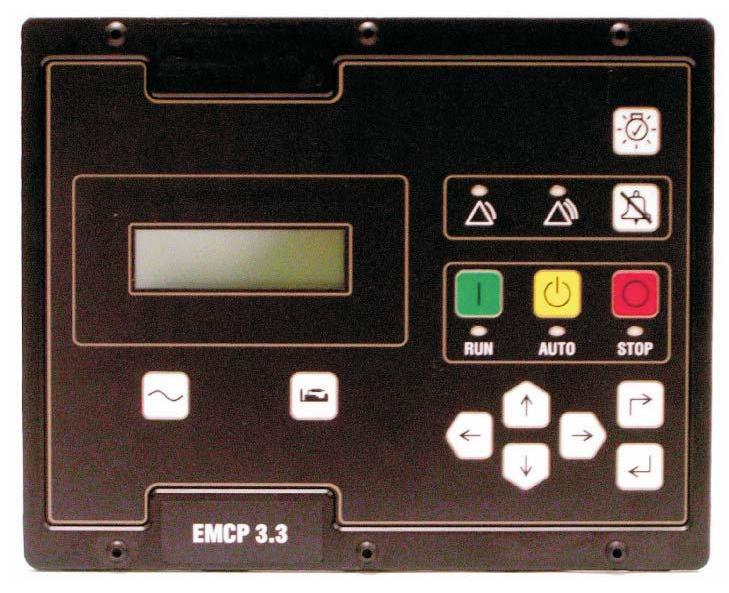
FRONT VIEW, DISPLAY SCREEN AND NAVIGATION KEYS
QUICK REFERENCE GUIDE
1
Navigation Keys
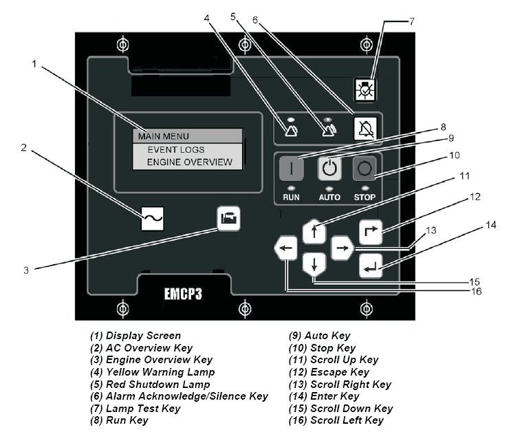
AC OVERVIEW The AC Overview Key (2) will navigate the display the first screen of AC information. The AC Overview Key information contains various AC parameters that summarize the electrical operation of the generator set.
ENGINE OVERVIEW The Engine Overview Key (3) will navigate the display to the first screen of engine information. The Engine Overview information contains various engine parameters that summarize the operation of the generator set.
ALARM ACKNOWLEDGE / SILENCE Pressing the Alarm Acknowledge/Silence Key (6) for 2 seconds will cause the horn relay output to turn off and silence the horn. This will change the alarm condition from “present” to “active”. Pressing the key will also cause any yellow or red flashing lights to turn off or to become solid depending on the active status of the alarms. The Alarm Acknowledge/Silence Key may also be configured to send out a global alarm silence on the J1939 Data Link which will silence alarm horns on remote Alarm Annunciators. The alarm or fault event must be rectified and cleared before resetting the system. The system must be in the STOP mode and all alarms must be “active” to allow alarm and fault reset functions. There are three ways to reset events, and details relating to alarm reset start on page 6 of this Quick Reference Guide. The most commonly used procedure is detailed on Page 8 of this Quick Reference Guide.
2
LAMP TEST Pressing and holding the Lamp Test Key (7) will cause all of the LED’s and the display screen pixels to turn on solid until the Key is released.
RUN Pressing the RUN Key (8) will cause the engine to enter the RUN mode (Manual Mode of Operation).
AUTO Pressing the AUTO Key (9) will cause the engine to enter the AUTO mode (for Remote Start / Stop Operation).
SCROLL UP The Scroll Up Key (11) is used to navigate up through the various menus or monitoring screens. The Scroll Up Key is also used during set point entry. During numeric data entry the Scroll Up Key is used in order to increment the digits (0-9). If the set point requires selection from a list, the Scroll Up Key is used to navigate through the list.
ESCAPE The Escape Key (12) is used during menu navigation in order to navigate up through the menu/sub-menu structure. Each key press causes the user to move backwards/upwards through the navigation menus. The Escape Key is also used to cancel out of data entry screens during set point programming. If the Escape Key is pressed during set point programming, none of the changes made on screen will be saved to memory.
SCROLL RIGHT The Scroll Right Key (13) is used during set point adjustment. During numeric data entry, the Scroll Right Key is used to choose which digit is being edited. The Scroll Right Key is also used during certain set point adjustments to select or deselect a check box. If a box has a check mark inside the box, pressing the Scroll Right Key will cause the check mark to disappear, disabling the function. If the box does not have a check mark inside the box, pressing the Scroll Right Key will cause a check mark to appear, enabling the function.
ENTER The Enter Key (14) is used during menu navigation to select menu items in order to navigate forward/downward in the menu/sub-menu structure. The Enter Key is also used during set point programming in order to save set points changes. Pressing the Enter Key during set point programming causes set point changes to be saved to memory.
DOWN The Down Key (15) is used to navigate down through the various menus or monitoring screens. The Down Key is also used during set point entry. During numeric data entry the Down Key is used in order to decrement the digits (0-9). If the set point requires selection from a list, the Down Key is used to navigate down through the list.
The Scroll Left Key is also used during certain set point adjustments to select or deselect a check box. If a box has a check mark inside the box, pressing the Scroll Left Key will cause the check mark to disappear, disabling the function. If the box does not have a check mark inside the box, pressing the Scroll Left Key will cause a check mark to appear, enabling the function.
3
STARTING THE ENGINE Once the control is configured correctly, the control panel is powered up, and the generator set is ready to be operated, the generator set can be started.
There are several ways the generator set can be started from the control panel.
1. To START the engine for MANUAL OPERATION: - Press the RUN KEY, to operate the system in Manual Mode.
2. Place the control in AUTO mode, for automatic start / stop function.
Then the engine can be started THREE DIFFERENT WAYS (via interface with a remote start initiation contact).
a: Activate DIGITAL INPUT #2, which is the REMOTE INITIATE INPUT. b: Activate a REMOTE INITIATE over the MODBUS data link (register number 1055).
c: Configure a PROGRAMMABLE CYCLE TIMER. When the control panel initiates a start command on a diesel engine, the control checks to make sure there are no SHUTDOWN EVENTS present (labeled PRESENT) or that there are no latched SHUTDOWN EVENTS (labeled ACTIVE).
If there are no shutdown events that are active or present, and after any pre-crank or start-aid activities have completed, the starter motor and fuel control will be activated.
The engine will continue to run whenever there is a remote start initiated and the Auto mode key has been pressed.
STOPPING THE ENGINE Once the engine is started, the engine can be stopped by pressing the STOP KEY on the control panel.
If the control is in AUTO, the engine can also be stopped by DEACTIVATING all of the remote initiate commands. There are three possible sources for this command: 1. The remote initiate input (digital input #2) which is the REMOTE INITIATE INPUT. 2. The remote initial command over the MODBUS Data link (register number 1055). 3. The Programmable Cycle Timer
Once the STOP command is issued, the control will go into COOLDOWN MODE. Cooldown mode will run for the duration of time that it is programmed in the COOLDOWN DURATION set-point (Normally set for 3 - 5 minutes). If the cooldown time is set for zero minutes, the engine will stop immediately.
The cooldown timer can be overridden by pressing and holding the STOP KEY for 5 seconds. The display will show a splash screen that will ask if you want to BYPASS COOLDOWN? or continue with the cooldown cycle.
If the ENTER KEY is pressed from the splash screen, the cooldown timer will be bypassed.
If the ESCAPE KEY is pressed from the splash screen, the cooldown cycle will continue until the programmed cooldown time has elapsed.
4
ALARM INDICATORS
YELLOW WARNING LIGHT A flashing yellow light indicates that there are unacknowledged active warnings. A solid yellow light indicates that there are acknowledged warnings active. If there are any active warnings, the yellow light will change from flashing yellow to solid yellow after the Alarm Acknowledge/Silence Key (6) is pressed. If there are no longer any active warnings, the yellow light will turn off after the Alarm Acknowledge/Silence Key (6) is pressed.
RED SHUTDOWN LIGHT A flashing red light indicates that there are unacknowledged active shutdown events. A solid red light indicates that there are acknowledged shutdown events active. If there are any active shutdown events the red light will change from flashing red to solid red after the Alarm Acknowledge/Silence Key (6) is pressed. Any condition that has caused a shutdown event must be manually reset. If there are no longer any active shutdown events, the red light will turn off.
5
ALARM ACKNOWLEDGMENT. To acknowledge any alarm or fault/shutdown event, press the “BELL” symbol pushbutton on the EMCP3 Display Panel for 2 seconds. This will change the condition from “present” to “active”. The alarm or fault event must be rectified and cleared before resetting the system. The system must be in the STOP mode and all alarms must be “active” to allow alarm and fault reset functions. There are three ways to reset events. The most commonly used is detailed on Page 8 of this Quick Reference Guide. 1. RESETTING INDIVIDUAL EVENTS FOR THE EMCP 3 GSC. This applies to the EMCP 3 GSC only. The basic process is to reset individual events by navigating to the desired event in the event log. To reset individual events on the EMCP 3 GSC, start by navigating to the event log: From the top of the Main Menu, enter Event Logs by pressing the Enter key.
FROM: MAIN MENU Select
EVENT LOGS by pressing the
ENTER KEY
Scroll up or down to select the desired log and
Press ENTER KEY
Press ENTER KEY to view the event details.
Pressing the
ENTER KEY will RESET the event. Next, select the log that contains the event that needs to be RESET.
In this example image, there are only two PRESENT or ACTIVE events, and they are both in the GENSET CONTROL log.
Events are ordered by the status of the event; PRESENT events are listed first, followed by ACTIVE events, and finally the INACTIVE events.
If the control is in STOP mode, RESET will be shown and highlighted. NOTE: If the event status is present, the RESET text will not be visible and the event cannot be reset until the condition that caused the event has been addressed.
6
2. RESETTING ALL EVENTS FOR A SINGLE MODULE The second way, which applies to all modules other than the EMCP 3 GSC, is to reset all events in that modules event log by navigating to one of the active events in the event log. With any method, you must be in STOP mode. A key difference between the EMCP 3 GSC and all other modules is that the other modules don’t display a PRESENT status for events. Events are shown as ACTIVE if they are currently affecting the system, or as INACTIVE if they are not. To reset all of a modules events on any individual module except the EMCP 3 GSC (listed as GENSET CONTROL in the event log), start by navigating to the event log.
FROM: MAIN MENU Select
EVENT LOGS by pressing the
ENTER KEY
Scroll up or down to select the desired log and
Press ENTER KEY Next, select the log which contains the event that needs to be reset. In this example image, there is only one ACTIVE event, and it is in the ENGINE CONTROL log.
Press ENTER KEY to view the event details.
Pressing the
ENTER KEY will RESET all events. Events are ordered by the status of the event; ACTIVE events are listed first, followed by the INACTIVE events. Scroll up or down through the list of events and find the ACTIVE event that requires resetting.
If the control is in STOP mode, and engine speed is zero, RESET ALL will be shown and highlighted.
Pressing the enter key will reset all of the ACTIVE events in that module’s event log that can be reset. NOTE: Modules other than the EMCP 3 GSC cannot display events as PRESENT. So if pressing ENTER KEY at RESET ALL doesn’t reset all of the events, the condition causing the event being viewed may still be present. For example, if the engine shut down on high coolant temperature, then the events will not reset until the coolant temperature drops below the shutdown threshold.
7
3. RESETTING ALL EVENTS FOR ALL MODULES The third way to reset events is a shortcut to reset all events for all modules. With any method, you must be in STOP mode. Once all of the events have been viewed and the condition(s) that are causing the events have been corrected, all active events (those for which the condition is not present) on all modules can be reset using the RESET ALL EVENTS feature. In order to do this, the control must be in STOP mode and engine speed should be zero.
FROM ANY SCREEN: Press the and hold the
ACKNOWLEDGE for approximately 5 seconds.
Pressing the
ENTER KEY Pressing the
ESCAPE KEY A confirmation prompt will appear. will continue and RESET all events on all modules.
will CANCEL the reset operation.
NOTE: Reset All Events will not reset Present events! For example, if the E-Stop switch is pressed and an EMERGENCY STOP SWITCH ACTIVATED SHUTDOWN is present, it cannot be reset until the E-Stop is pulled out and the event status changes from PRESENT to ACTIVE.
TROUBLESHOOTING RESETTING EVENTS
There are common reasons for the EMCP 3 GSC not allowing events to be reset. First of all, in order to reset any event, the EMCP 3 GSC must be in STOP mode. In order to reset engine ECM events, the engine speed must also be zero. One common confusion about events is the SERVICE MAINTENANCE INTERVAL WARNING. This event is explained below. If a SERVICE MAINTENANCE INTERVAL WARNING is PRESENT, it cannot be reset. The warning is PRESENT because the countdown timer has reached zero. To clear the warning, the timer must be reset, rather than the event. When the timer is reset, it returns to the programmed interval (factory default is 180 calendar days or 500 engine hours). This timer must be reset from the display; it cannot be reset by using the Service Tool alone. NOT IN AUTO is another event that can cause confusion is NOT IN AUTO. This event is Present whenever the control is in either RUN or STOP. As a result, it can not be reset in STOP (as the event is present). It will be Active when the control is in Auto and Present when the control is in STOP. The event will reset when the control is returned to AUTO
8
Grammer Actimo XXL Pneumatic Suspension Operating Instructions
! IMPORTANT:
Read and understand this Grammer seat instruction manual before operating
• For control system adjustments see enclosed instructions • Adjust the suspension to accommodate your weight before operating • If equipped with seat restraint, insure it is fastened before operating • Adjust the seat and seat system to your personal comfort preference before operating • Do not adjust seat or seat system while operating this equipment • Immediately report any malfunction or concern about the seat /seat system to your supervisor • Under no conditions should you operate equipment that is in disrepair or malfunctioning
IMPORTANT!
Seating and Seat System Disclaimer can be found on our website at: www.jrmerritt.com/seatdisclaimer

Distributors for Grammer, Inc.
Stratford, CT www.jrmerritt.com 203-381-0100 Fax: 203-381-0400
Rev. 9/15/10
Contents
General instructions .................................................................................... 20 Safety instructions....................................................................................... 20 Connecting data .......................................................................................... 22 Guarantee and liability ................................................................................ 22 Seat functions and operation ...................................................................... 23 W eight adjustment .............................................................................. 23 Height adjustment ............................................................................... 23 Seat pan angle adjustment ................................................................. 23 Seat depth adjustment ........................................................................ 24 Absorber.............................................................................................. 24 Armrest adjustment * .......................................................................... 24 Armrests * ** ...................................................................................... 25 Headrest * ** ...................................................................................... 25 Seat heater * ** ................................................................................... 25 Lumbar support ................................................................................... 26 Backrest adjustment ........................................................................... 26 Fore/aft isolator ................................................................................... 26 Fore/aft adjustment ............................................................................. 27 Maintenance ............................................................................................... 28
* if fitted ** optional extra
The operating instructions must be read in full before use. The operating instructions must be kept in the vehicle and always be at hand. The driver’s seat may only be fitted, serviced and repaired by specialist personnel. The respective national regulations and the vehicle manufacturer’s fitting instructions must be observed. The national fitting regulations can be obtained from GRAMMER AG or from agencies of the company, or from the vehicle manufacturer. A correctly functioning and individually adjusted driver's seat is essential to your health. Take adequate care of your seat and have it serviced regularly to ensure that it functions correctly. The functional checks are to be carried out at least as regularly as vehicle services (see maintenance plan for vehicle).
These operating instructions should always be kept with the driver's seat. If the seat is passed on to a third party, it must be accompanied by the relevant operating instructions. Subject to modifications serving engineering progress and deviations compared to the standard type seat arising therefrom.
Driver's seats that have been adjusted incorrectly have a smaller moving area. In order to prevent any personal injury, the seat must be adjusted for the driver's weight
and .
To prevent injury, seat.
of the driver's
of the driver’s seat, possible has to be removed from the seat cushion and the backrest upholstery.
To eliminate any risk of accident, the settings must be checked to ensure they are
correctly engaged .
Adjustments must be made .
, the backrest frame must be supported, for example held in place, before the backrest adjuster is operated. If you fail to do so, there is a danger that the backrest frame may jerk forward and .
(for example fitting parts which are not original
AG parts) may impair the safety standard to which it has been tested.
, threatening your must be approved by . For this reason, AG. During the removal and installation of the driver’s seat, the corresponding instructions by the specific vehicle manufacturer must be strictly observed! Do not hold onto the covers for lifting the driver's seats. If you do so anyway, there is an
. Before you remove the driver’s seat, disconnect all plug-in connections between the seat and the vehicle supply network. When you replace the plug-in connectors, make sure they are tight (dust, water). Seatbelts are fitted or can be retrofitted to the driver’s seat. Seatbelts
, as they increase the load in the seat mounting area. Seatbelts must be fitted in accordance with specific national regulations and guidelines, and must be approved by AG. Seatbelts must be fastened .
after an accident. Where seatbelts are fitted to the driver's seat, the and must be checked by specialist personnel after an accident has occurred.
Fasteners must be . If the seat wobbles, there may be loose bolts or other faults.
If you notice that the seat does not function correctly (for example a defective suspension of the driver's seat; improper curvature of the lumbar support or damaged bellows),
to arrange for repairs to be carried out. If you fail to do so, your health may be affected and the . Before the vehicle is used, switches that might be in the seat (for shutting down mechanical equipment when the driver leaves his/her seat) must be checked for
. If malfunctions are detected, the vehicle must not be driven. – –
(e.g. with a built-in switch) except for the driver’s weight during normal use, as the vehicle may otherwise start to move by itself. – –
If you take off the weight from the seat while driving, this will cause the vehicle to stop. –Do not indent the bellows while there is load on the driver’s seat. –
Make sure that the . remains free of or
The driver’s seat is and must be protected against splashes of water! Any conversion or refitting work on a exclusively in by AG driver’s seat must be performed or and in adherence with the applicable operating, maintenance and installation instructions and in compliance with all relevant national regulations.
bear the risk of
or
and the proper function of the driver’s seat or mounted parts can no longer be guaranteed. The driver’s seat is . Worn parts such as rollers, shock absorbers and the fixation must be checked from time to time.
of the vehicle. you must check if all seat settings selected guarantee a
If you need to connect cables to the vehicle supply network, strictly observe the following instructions:
an fitted in the driver’s seat (e. g. the seat heater or the seat ventilation), you must obtain the relevant electrical data for the respective vehicle with reference to voltage, protection and the kind of connections from the manufacturer, from AG or the company’s agencies. For safety reasons, the installation and connection to the vehicle supply network must be carried out by authorized specialist personnel only. The seat connections must be protected independently of other vehicle components.
12V 10A 20A
24V 7,5A 10A
For building an electric connection, select an electric circuit by means of which the electric consumers of the driver’s seat are separated from the live network when
GRAMMER AG does not disclaim any guarantee or liability for damage resulting from incorrect assembly, use or repair of the seats. Further details on the guarantee granted by GRAMMER AG are stated in your contractual documents (see invoice or delivery note). Guarantee claims against AG beyond the guarantee obligations described there are excluded.


The seat must be adjusted for the driver’s weight by briefly pulling the actuator lever of the automatic weight and height adjuster (arrow) with the vehicle at a standstill and the driver sitting on the seat. The driver must sit absolutely still during adjustment. Before adjusting the weight, adjust shock absorbers to the position “soft”. To prevent damage to the health, the setting for the driver’s weight must be checked and adjusted individually before the vehicle is driven.
The seat height can be set pneumatically and is continuously adjustable. The seat height can be altered by pulling or pushing the adjustment lever fully up or down (arrow). If the adjustment reaches the top or bottom endstop, the height is adjusted automatically in order to guarantee a minimum spring travel. Before adjusting the height, adjust shock absorbers to the position “soft”. In order to avoid damage, do not operate compressor for more than 1 minute
The angle of the seat pan can be individually adjusted. To adjust the angle of the seat pan, pull the left handle upwards. By exerting pressure on or off the front or rear part of the seat pan it can be moved to the desired position.
* if fitted ** optional extra

With the upper and lower switch the curvature in the upper and lower area of the backrest upholstery can be individually adjusted. This increases both the seating comfort and the performance of the driver. The lumbar support curvature can be increased pressing "+" or reduced by pressing "–" on the relevant switch. When the backrest upholstery does no longer react to pressing "+", the maximum curvature has been reached and the switch should be released.

Pull up the locking lever to release the backrest catch. When releasing the backrest catch, do not apply load to the backrest by pressing against it. By exerting pressure on or off the front or rear part of the seat pan it can be moved to the desired position. Release the locking lever to lock the backrest. It should not be possible to move the backrest into another position after it has been locked.


Under certain driving conditions (for example with a trailer attached), it is useful to activate the fore/aft isolator. This means that shock impacts in the driving direction can be better absorbed by the driver seat. Position = fore/aft isolator off Position = fore/aft isolator on After the adjustment of position , the locking lever must latch into the desired position. For that, the seat must be pressed backwards until it latches with an audible click. It should not be possible to move the fore/aft isolator into another position when it is locked.
* if fitted ** optional extra


Dirt can impair the function of the seat, So make sure you keep your seat clean. Upholstery does not need to be removed from the seat frame for cleaning.
: Do not clean the seat with a pressure washer! When cleaning the upholstery, make sure the upholstery is not soaked. Use standard commercially available
on a small, concealed
area.