11 minute read
STEERING AND IMPLEMENT HYDRAULIC SYSTEMS


416D CENTER PIVOT BACKHOE LOADER HYDRAULIC SYSTEM
PUMP
END COVER
E-STICK
STICK
BUCKET
SWING
BOOM
AUX
INLET MANIFOLD
RIGHT STABILIZER LEFT STABILIZER
MANIFOLD LEVER
LEVER COOLER
BACK FLOW CHECK VALVE
S T E E R L I F T T I L T A U X TANK
SMU
• 416D hydraulic system:
- Center pivot
- Mechanical controls 41
STEERING AND IMPLEMENT HYDRAULIC SYSTEMS
The "D" Series backhoe hydraulic systems incorporate many of the improvements made to late production "C" Series.
The illustration represents the 416D steering and implement hydraulic system.
The steering and implement pump, the pump control and most of the implement control valves function essentially the same. The biggest difference to the implement valves is that on some models they are pilot operated. Also, on some models the operating pressures have also been increased.
On the "D" Series, the stabilizer valves are pilot controlled and are of a different design from previous backhoe loader stabilizer valves.
The steering system features dynamic signal bleed as did the late production "C" Series. With the dynamic bleed and the steering in HOLD, the steering priority spool bleeds oil through the steering metering unit (SMU) signal line and SMUback to the tank. When the steering wheel is turned, this signal bleed oil shifts the priority spool to direct pump supply oil to the SMU resulting in faster steering response than systems without dynamic bleed.
The hydraulic tank has also been redesigned. An expansion tank is no longer required.
The backflow check valve has been relocated. The valve now restricts return flow from all implement valve groups. On previous backhoes, the valve only worked with the backhoe valve group. The valve assists in preventing cylinder voiding. The check valve does not affect return oil from the SMU.
The other major difference in the hydraulic system is the signal network routing, which is referred to as "reverse signal path." The signal network will be described later in this presentation.
NOTE: The colors on the hydraulic schematics and cross-sectional views shown throughout this presentation denote various pressures within the system. The legend of color codes is as follows:
Red - pump supply pressure Red and white stripes - reduced pump supply pressure, circuit pressure or load sensing pressure Red hatch - further reduced pump supply pressure, circuit pressure or load sensing pressure Pink - lowest pump supply pressure, circuit pressure or load sensing pressure Orange - signal or pilot pressure Orange and white stripes - a lower signal or pilot pressure Orange hatch - further reduced signal pressure Green - line open to the tank Blue - blocked oil Yellow - moving part or active valve envelope.
For metering situations more than one envelope may be highlighted in yellow.
424D / 428D / 438D SIDE SHIFT BACKHOE LOADERS HYDRAULIC SYSTEM
SIDESHIFT LOCK PISTONS
END COVER
E-STICK
STICK
BUCKET
SWING
BOOM
AUX
INLET MANIFOLD SHUTOFF
RIGHT STABILIZER LEFT STABILIZER
MANIFOLD PUMP
TANK
LEVER
LEVER COOLER
BACK FLOW CHECK VALVE
S T E E R L I F T T I L T A U X SMU
• 424D, 428D and 438D hydraulic system:
- Sideshift machines
- Mechanical controls 42
The 424D, 428D and 438D sideshift machines have similar components as the center pivot machines. The sideshift machines are equipped with sideshift lock pistons.
The 424D is not available with two loader bucket tilt cylinders as shown here.
Some countries require a shutoff valve to block the flow of oil to the backhoe valve group when the machine is roaded to prevent unintentional implement movement. Center pivot machines may also be equipped with this feature.
The shutoff valve is an option on those machines with mechanical implementcontrols only.
420D / 430D CENTER PIVOT BACKHOE LOADERS HYDRAULIC SYSTEM
PARALLEL LIFT
PUMP
END COVER
E-STICK
STICK
BUCKET
SWING
BOOM
AUX
INLET MANIFOLD PATTERN CHANGER JOYSTICK
JOYSTICK TANK
COOLER
BACK FLOW CHECK VALVE
JOYSTICK SMU
RIGHT STABILIZER LEFT STABILIZER
MANIFOLD LEVER
LEVER S T E E R L I F T T I L T A U X
PILOT SHUTOFF
RIDE CONTROL
• 420D and 430D hydraulic system:
- Center pivot machines
- Pilot controls 43
The backhoe valves on the 420Dand 430Dare pilot operated. If the machine is equipped with ITlinkage, as shown, then the loader valves are also pilot operated. With pilot operated machines a pilot accumulator is used to provide dead engine lowering capability for a limited time after engine shutdown.
These machines ship with the excavator control pattern. Machines can be ordered with the standard backhoe control pattern or ordered with an optional pattern changer valve.
If the machine is equipped with the single tilt cylinder bucket, the loader valves are operated through mechanical linkage instead of a pilot joystick.
The pilot shutoff valve blocks the oil from the joysticks to prevent movement of an implement. The shutoff valve eliminates the need of the optional hydraulic shutoff valve available on machines with mechanical controls only.
432D / 442D SIDESHIFT BACKHOE LOADERS HYDRAULIC SYSTEM
PARALLEL LIFT
SIDESHIFT LOCK CYLINDERS PUMP
END COVER
E-STICK
STICK
BUCKET
SWING
BOOM
AUX
INLET MANIFOLD PATTERN CHANGER JOYSTICK
JOYSTICK TANK
COOLER
BACK FLOW CHECK VALVE
JOYSTICK SMU
RIGHT STABILIZER LEFT STABILIZER
MANIFOLD LEVER
LEVER
PILOT SHUTOFF S T E E R L I F T T I L T A U X
RIDE CONTROL
• 432D and 442D hydraulic system:
- Sideshift machines
- Pilot controls 44
The backhoe valves on the 432Dand 442Dare pilot operated. The loader valves are also pilot operated since the standard version of these models feature the IT linkage.
The single tilt cylinder bucket is optional. With this option the loader valves are operated through mechanical linkage.
Ride control is an option that is available for all "D" Series backhoes. Hose routing and the system design has changed from the "C" Series.
MECHANICAL CONTROLLED LOADER VALVES
PUMP CONTROL VALVE AUX BOOM BACKHOE SECTION
SWING BUCKET STICK E-STICK
ORIFICE
TORQUE LIMITER
CONNECTED TO SWASHPLATE
LOADER AUX.
PRIMARY RESOLVER
SECONDARY RESOLVER LOADER TILT LOADER LIFT SMU
LOADER SECTION
LEFT STABILIZER
RIGHT STABILIZER
• Signal network:
- Reverse signal path
- Affects resolver troubleshooting
- Orificed steering resolver
- Orifices in loader primary resolvers 45
On most generations of backhoes, the signal line was routed from the backhoe section, to the loader section and then to the pump. Late production "C" Series had a variation from this with a signal line from the backhoe section and a signal line from the loader section being connected to a tee which was equipped with a resolver. The highest resolved signal between the two valve sections then flows to the pump.
With the "D" Series, the last resolver in the network is in the loader auxiliary circuit. The signal flows from the loader section, to the stabilizer section, to the backhoe section, before going to the pump control valve. This routing is reverse of previous backhoe signal networks.
Resolver troubleshooting procedures are affected by this change. A secondary resolver problem in the loader section will no longer have an affect on the backhoe section.
The orifice in the steering resolver in the loader section results in a larger pressure differential across each loader resolver orifice when a loader implement is activated and the torque limiter opens, as compared to a backhoe implement. This difference in pressure results in a reduced signal to the torque limiter and pump compensator.
This action provides for lower pump flow to the loader section for a given circuit pressure when the torque limiter opens, which results in a lower available torque for the loader section than what is available for the backhoe section. This change was done to further improve loader and backhoe performance.
Backhoe implements (except for the auxiliary circuits) do not have orifices in their primary resolvers and are not affected by the orifice in the steering resolver.
An additional orifice was added between the backhoe valve section and the orifice in the torque limiter for the "D" Series backhoe to further improve machine performance.
PILOT CONTROLLED LOADER VALVES
PUMP CONTROL VALVE PRIMARY RESOLVER AUX BOOM BACKHOE SECTION
SWING BUCKET STICK E-STICK
ORIFICE
TORQUE LIMITER
CONNECTED TO SWASHPLATE SECONDARY RESOLVER
LOADER AUX. LOADER TILT LOADER LIFT SMU
LEFT STABILIZER
RIGHT STABILIZER
LIFT PILOT VALVE LOADER SECTION
PILOT OIL
• Signal network:
- Pilot operated loader valves 46
On machines with pilot operated loader valves, the pilot valve for the loader lift circuit is also part of the signal network.
The lift pilot valve directs some pilot oil through the resolver network to upstroke the pump when the loader is in FLOAT.
This pilot signal through the signal network causes the pump to increase pump standby pressure to make sure that pilot system pressure remains high enough to hold the lift spool in the FLOATposition.
NOTE: Since the maximum pilot pressure is limited, the pump receives a virtually fixed signal from the pilot system when the lift spool is shifted to FLOAT. This increase in pump supply and signal pressure can be checked at the pump outlet test fitting and the signal test fitting. There is no recommended specification or test for this.
2
3 1
4
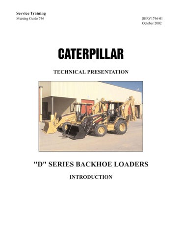
• Hydraulic system components:
1. Hydraulic tank
2. Sight gauge
3. Steering Metering
Unit (SMU)
4. Drain tube 47
The hydraulic tank (1) is located between the engine and the cab.
With the relocation of the brake master cylinders, the hydraulic tank was redesigned for increased capacity. With the increase in capacity the overflow or expansion tank is no longer required.
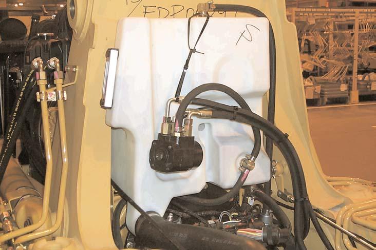
5 6
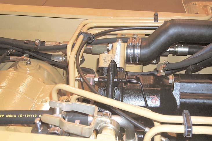
4 3 1
2
• Hydraulic system components:
1. Hydraulic filter
2. Steering and implement pump
3. Pump control valve
4. Signal pressure test fitting
5. Loader valve group
6. Back flow check valve
• Pump and system tests 48
In the pump control valve (3) are two spools. The flow compensator (margin spool) regulates output flow in response to the load signal received through the signal network. The flow supplied by the pump will be the amount of flow required to keep supply pressure at a fixed value above the signal pressure. The difference between supply pressure and the signal pressure is called "margin pressure." The flow compensator also controls low pressure standby pressure.
The pressure cutoff spool in the pump control valve limits maximum system pressure and serves as the relief valve for the system.
The back flow check valve (6) is part of the fitting just before the hydraulic filter (1). The check valve helps reduce cylinder cavitation.
Before performing any pump tests or making adjustments to the pump control valve, measure and record the machine cycle times. If the cycle times are within specification, checking low pressure standby or margin pressure may not be required unless the system is overheating. Cycle time checks will also indicate if all or some of the implements in the system are operating within specification.
This information can be helpful in determining if the pump or the implement is at fault. If all cycle times are too slow, margin pressure and low pressure standby may be set too low. If the machine is too responsive, the margin pressure and low pressure standby may be set too high.
The pump supply pressure test fitting (not shown) can be used to check maximum system pressure or low pressure standby. The fitting can be accessed from below the operator's compartment.
Use the signal pressure test fitting (4) to check the signal pressure or the maximum steering pressure. Signal pressure is compared to pump supply pressure to determine the margin pressure.
All return oil from the implements and steering flows back to the filter through the backflow check valve. Due to the dynamic bleed steering, low pressure standby is over 700 kPa (100 psi)higher than on most "C" Series backhoes.
NOTE:Due to the signal pressure limiter, the steering circuit is commonly used to check margin pressure because the steering circuit pressure is below maximum system pressure.
Engineering is recommending a slightly different procedure for checking margin pressure on "D"machines. The latest recommendation is to lock the boom and move the boom lever about one third travel in the DOWN position.
If Standby Pressure is adjusted to about 3100 kPa (450 psi) or slightly higher, the need to adjust a check margin pressure may not be necessary.
Also, on the "D" Series, engineering is suggesting that circuit and system stall pressures be checked at the signal pressure test fitting. By doing this the confusion related to checking circuits with lower pressure settings than the pressure cutoff on the pump may be eliminated. For circuits with higher line relief settings than the pressure cutoff, the pressures read at either test port should be the same.
49
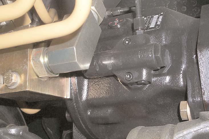
• Hydraulic system components:
- Torque limiter (arrow) A torque limiter (arrow) is used to control the pump. The torque limiter will reduce maximum pump flow available as pressures increase to prevent engine stall.
The torque limiter provides improved hydraulic system performance with less engine horsepower. The torque limiter is adjustable. Before making adjustment to the torque limiter, make sure low idle is set correctly.
NOTE: A quick check to make sure the torque limiter is operating correctly on single tilt cylinder machines, is to operate the machine at low idle. With the machine at normal operating temperatures, apply the service brakes and select SECOND FORWARD. Turn on air conditioner (if equipped) and accessories. Raise and rack back the bucket. If the engine stalls, the torque limiter may need to be adjusted.
For dual tilt cylinder machines, follow the same steps, except stall the bucket in the dump position, instead of racking back.
For more precise adjustment of the torque limiter follow the procedures in the service manual. A torque converter stall test should also be done before adjusting the torque limiter. The engine may not be performing correctly.