8 minute read
Fuel System


FUEL RETURN CHECK VALVE
ROLLERS
PLUNGERS FUEL HYDRAULIC SYSTEM
ENGINE RUNNING
BOOST PRESSURE
BOOST CONTROLLER
TORQUE TRIMMER
CAM RING FUEL TANK
WATER SEPARATOR
VENT ORIFICE INJECTOR
ROTOR MAIN FILTER
FEED PUMP
SHUTOFF SOLENOID
DELIVERY VALVE
METERING VALVE TRANSFER PRESSURE REGULATOR
SHOES
SCROLL PLATES AUTOMATIC ADVANCE MECHANISM
ORIFICE CHECK VALVE COLD ADVANCE DEVICE HYDRAULIC HEAD
LIGHT LOAD ADVANCE VALVE FLAT
LATCH VALVE TRANSFER PUMP
• Fuel flow through fuel system:
-Water separator/fuel filter
- Lift pump
- Fuel filter
- Distributor-type fuel injection pump
- Injectors
- Return to tank 19
Fuel System
All components shown in the schematic except for the fuel tank, water separator/fuel filter, lift pump, fuel filter and injector are part of the fuel injection pump.
The feed or lift pump is used to move fuel from the fuel tank to a higher level on the machine. The pump is also used to prime the system.
The water separator removes water from the fuel. Since the fuel injection pump is lubricated by fuel, it is extremely important that water does not enter the pump. Water will cause the pump to malfunction and will lead to the rotor and plungers locking up. The water separator should be serviced daily.
The transfer pump draws fuel from the tank and supplies fuel to the injection pump.
The hydraulic head is machined with bores and passages which allow fuel to flow to and from a specific point. For example, fuel flows from the transfer pump to the metering valve or from the metering valve to the inlet passage to the rotor.
The rotor is located in the hydraulic head. The rotor distributes fuel to the delivery valves. The rotor has four inlet passages and one outlet passage. As the rotor turns, fuel enters the passages in the rotor and forces the plungers in the drive end of the rotor outward. As the rotor continues to turn, the inlet passage closes. As the plungers are forced inward by the cam ring and rollers, the fuel pressure in the rotor increases. At the same time, the outlet passage opens and fuel exits the rotor through the delivery valves to the injectors.
The transfer pressure regulator controls the fuel transfer pressure within the injection pump. Transfer pressure will increase as engine speed increases. The regulator also permits the fuel to bypass the transfer pump when the fuel system is being primed.
The shutoff solenoid allows fuel to enter the fuel injection pump when the solenoid is energized. When the key start switch is moved to the OFF position, the solenoid is de-energized and a spring moves the plunger in the solenoid to block fuel flow.
The metering valve controls the amount of fuel to the hydraulic head or rotor. The valve is connected to a mechanical governor and the throttle or governor control lever. As the metering valve is rotated within the hydraulic head, a delivery control groove in the valve precisely meters fuel to the rotor.
A tapered flat on the metering valve works with the light load valve. The flat is machined in line with the delivery control groove.
The light load advance valve and metering valvework with two control orifices in the hydraulic head to override the normal speed advance system. During low load conditions, the outward travel of the rollers and shoes is reduced during the rotor filling cycle, which delays the point of roller contact with the cam lobes resulting in retarded injection.
The light load advance compensates for this delay by advancing injection at reduced fuel levels. Passageways are drilled within the hydraulic head body to connect the metering valve "flat" with the pressure end of the advance device (through a second control orifice)and the pump cambox.
As the metering valve is rotated in the hydraulic head by the governor, a larger or smaller flow path from the advance piston to the cambox is created. The relationship between the "flat" with the delivery control groove is arranged so that, as delivery is reduced, flow past the flat is also reduced. Thus, the pressure signal applied to the advance piston is increased to advance the timing.
The boost controller adjusts the maximum fuel delivery based on variations in the boost pressure from the turbocharger. As boost pressure increases, the scroll plates rotate and allow the plunger travel to increase. This action permits an increase in fuel delivery resulting in more engine horsepower.
The torque trimmer provides a means to regulate the volume of fuel being delivered at full load. The torque trimmer provides the maximum amount of fuel in the loadable range of the engine which can be burned smoke free.
The delivery valves are check valves which open to allow fuel from the pumping mechanism to the injectors. There is one delivery valve per injector. The valves rapidly reduce pressure in the injector lines at the end of the injection cycle to ensure a rapid closure of the injector nozzles and, in conjunction with the cam ring profile, maintain a residual pressure in the fuel lines to the injectors.
The latch valve prevents transfer pressure from reaching the automatic advance mechanism during cranking until the engine is started to prevent premature advance timing.
The automatic advance mechanism progressively advances the start of injection as engine speed increases. The automatic advance mechanism causes the cam ring to rotate in the pump housing. The spring in the mechanism moves the piston and cam ring to retard the timing, while transfer pressure sensed on the left side of the piston works against the spring to advance the timing.
The check valve prevents reverse fuel flow from the automatic advance due to cam loading. The orifice permits fuel to vent from the automatic advance when the engine rpm are reduced.
The cold advance device is used to reduce white smoke by advancing the engine timing to improve cold idling combustion capability. The cold advance device is sometimes called a "wax motor" and is a relatively slow response actuator.
At start-up, a check valve prevents transfer pressure from flowing to the right end of the automatic advance mechanism preventing the sleeve from moving away from the start advance position. This action prevents the spring from fully retarding the engine timing. After the engine is started and allowed to warm up to a specified temperature, a coolant switch closes and current is sent to the wax motor causing the wax to melt.
As the wax melts, it changes in volume and goes from a solid to a liquid. After approximately 25 seconds or more, the pin in the device moves to the left and unseats the check valve. Transfer pressure then flows to the right end of the automatic advance mechanism and moves the sleeve to the left against a stop to the normal automatic advance operating mode.
The fuel return check valve maintains a slight pressure in the fuel injection pump to ensure good lubrication. The fuel return check valve also allows hot fuel to bleed from the injection pump for cooling.
NOTE: Only the 430D, 438D and 442D backhoe loaders are equipped with a boost controller.
The various color codes which are used in this presentation to identify oil flow and pressures for the fuel hydraulic system are as follows:
Pink - Reduced transfer pressure
Red Dots - Transfer pressure
Red - High pressure fuel
Blue - Blocked fuel
Green - Suction or drain fuel
Purple - Boost air pressure
GOVERNOR SPRING
VENT ORIFICE
FUEL RETURN CHECK VALVE
SCROLL LINK PLATE
DRIVE SHAFT
SHIFTER AND SLEEVE
GOVERNOR FLYWEIGHTS
ROLLERS LOW IDLE STOP FUEL INJECTION PUMP
HIGH IDLE STOP THROTTLE LEVER
METERING VALVE
FUEL SHUTOFF SOLENOID
FUEL INLET
TRANSFER PRESSURE REGULATOR
SCREEN
TRANSFER PUMP
CAM RING AUTOMATIC ADVANCE MECHANISM SHOES TO INJECTOR
SCROLL PLATES
ORIFICE CHECK VALVE PLUNGERS
• Fuel injection pump 20
This illustration shows a sectional view of the fuel injection pump.
Fuel is drawn by the transfer pump through the pressure regulator and sent to the metering valve when the solenoid is energized. The fuel also flows through an annular groove around the rotor to the orifice check valve and the automatic advance mechanism.
The metering valve controls the amount of fuel sent to the pumping elements inside the rotor (plungers, cam ring and shoes). As the rotor turns, the cam ring forces the shoes and plungers in to increase the fuel pressure. The pressurized fuel is then directed to the injectors.
1
4
6 5
7 2
3
8
9
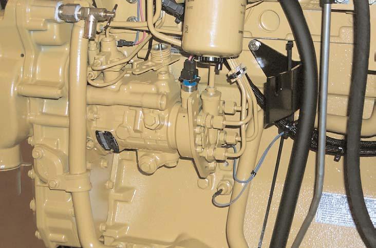
• Fuel injection pump components:
1. Boost controller
2. Fuel shutoff solenoid
3. Fuel transfer pressure regulator and inlet
4. Torque trimmer
5. Latch valve
6. Locking bolt
7. Automatic advance mechanism and cold advance device
8. Delivery valve
• Additional engine component:
9. Oil pressure switch 21
The fuel injection pump is locate on the left side of the engine. Only the 430D, 438D and 442D are equipped with a boost controller (1).
If a new pump is installed on the engine, a locking bolt (6) and a two position spacer in the pump flange below the timing mark on the pump engine flange must be loosened after installing the pump on the engine. In the locked position, the bolt prevents the pump drive shaft from turning. Move the spacer to provide additional clearance between the bolt head and the pump flange to unlock the pump drive shaft.
If this procedure is not performed, the fuel pump will be damaged if an attempt is made to start the engine. If the timing pin was used this bolt may not have been used to prevent the pump drive shaft from turning.
The oil pressure switch (9) can be removed to install a test nipple to check engine oil pressure.
NOTE: Refer to service manual module "Lucas Fuel Pump Supplement" (Form SENR6525) for more information on removing and installing the fuel injection pump.
This is the same type of fuel pump used on the 914G and IT14G.