3 minute read
CAB REMOVAL AND INSTALLATION


Template Date: 1994_04_29Template Name: OM_1_col
TRIM THIS EDGE
HANDLING THE MACHINE
1 2 3
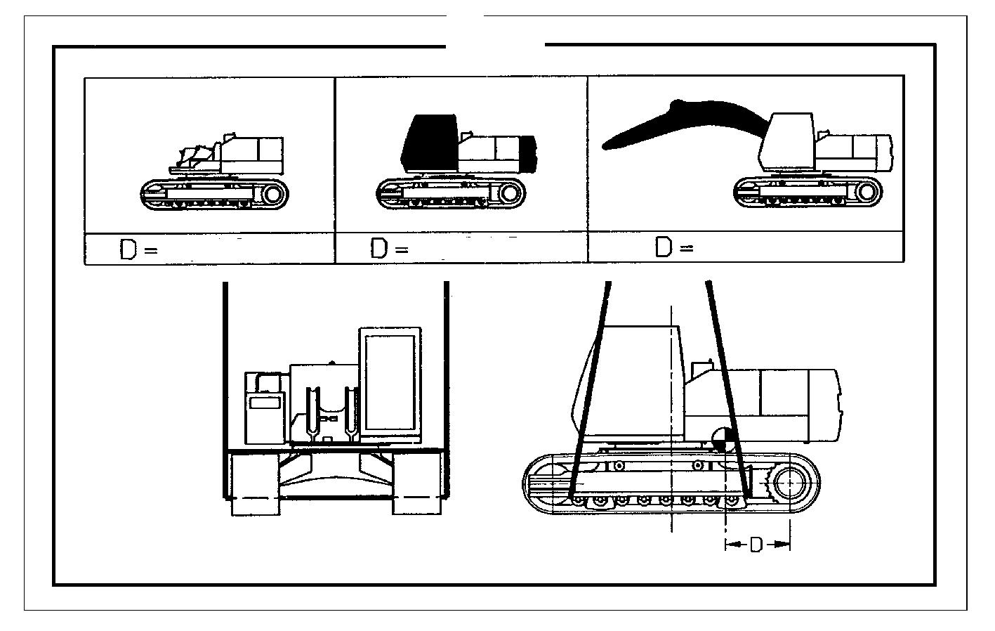
This decal shows the position of the centre of gravity in relation to the travel reduction gear centre-line. The centre of gravity distance (D) varies depending on the three possible handling configurations for the machine.
CS98M643
(1)Machine without boom, without cab and without counterweight. (2)Machine without boom, with cab and with counterweight. (3)Machine with monoblock boom, with cab and with counterweight. NOTE: Machine weights are given with 0.60 m track pads.
WARNING: The fixing points shown in the above decal must be observed.
788 series CK type
Distance (D) Machine weight (1).....................................................1.206 m.............................................8814 kg (2).....................................................0.809 m..........................................12 059 kg (3).....................................................1.086 m..........................................13 316 kg
788 series LC type
Distance (D) Machine weight (1).....................................................1.359 m.............................................9476 kg (2).....................................................0.984 m..........................................12 291 kg (3).....................................................1.238 m..........................................14 248 kg
988 series CK type
Distance (D) Machine weight (1).....................................................1.270 m..........................................10 892 kg (2).....................................................0.808 m..........................................14 778 kg (3).....................................................1.161 m..........................................16 448 kg
106
TRIM THIS EDGE
LEFT PAGE
988 Series Type CKE
Distance (D) Machine weight (1).....................................................1.269 m..........................................10 863 kg (2).....................................................0.806 m..........................................14 749 kg (3).....................................................1.160 m..........................................16 419 kg NOTE: For machines equipped with other track pad widths, consult your CASE Dealer.
WARNING: It is forbidden to handle the machine equipped with its dipper.
Counterweight fixing points Cab fixing points


PH07824
CD98E044 It is essential to use the load handling points to handle the counterweight. To remove the counterweight consult your CASE Dealer.
Weight of counterweight 788 Series ...............................2950 kg 988 Series ...............................3550 kg It is essential to use the load handling points to handle the cab. To remove the cab, see "Removing and installing the cab". Cab weight.................................291 kg
Dipper
To remove the dipper, consult your CASE Dealer. For the weight of the dipper, see "Weights" in the "Specifications" Section.
Boom
To remove the boom, consult your CASE Dealer. For the weight of the boom, see "Weights" in the "Specifications" Section.
107
TRIM THIS EDGE
RIGHT PAGE TRIM THIS EDGE
Template Name: OM_1_colTemplate Date: 1994_04_29
Template Date: 1994_04_29Template Name: OM_1_col
TRIM THIS EDGE
CAB REMOVAL AND INSTALLATION Removal
STEP 3
Tools required
-One 10 mm wrench for hexagonal head screws -One 22 wrench for hexagonal head screws -Lifting equipment NOTE: The weight of the cab is 291kg.
STEP 1
Park the machine on flat, horizontal ground.
STEP 2
PH07911 Disconnect the power socket from its base. Install the plug on the base. Disconnect the windshield washer hose. Disconnect the radio aerial (if fitted).
STEP 4
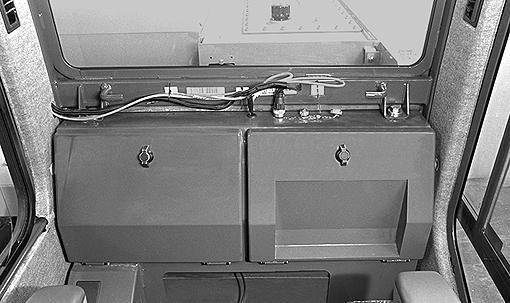
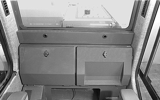
PH07909 Remove the trim panel behind the seat.
PH07824 Remove the two plastic plugs from the cab roof and install a suitable lifting device.
108
TRIM THIS EDGE
LEFT PAGE
STEP 5 STEP 8
PH07911
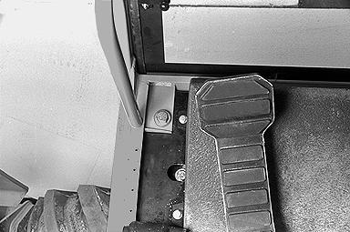
PH00305 Remove the four cab retaining screws. NOTE: The floor mat has to be lifted to gain access to the screws at the front of the cab.
STEP 6
Raise the cab carefully until it is completely clear of the machine.
STEP 7
Lower the cab to the ground, resting it on wooden blocks.
PH07824 Remove the lifting equipment and install the two plastic plugs.
Installation
Tools required
-One 10 mm wrench for hexagonal head screws -One 22 wrench for hexagonal head screws -Lifting equipment
STEP 1
PH07824 Remove the two plastic plugs from the cab roof and install the lifting equipment.
109
TRIM THIS EDGE
RIGHT PAGE TRIM THIS EDGE