8 minute read
Tram reach gear set.....................................................5

tram case removal Tram reach gear set removal and installation
Advertisement
To remove the tram reach gear set:
1. Lower the conveyor tail section until it is level with the floor.
2. Raise the gathering head and cutter head assemblies and place a small stack of blocking under each.
WARNING! You could be seriously injured or killed by falling loads. Observe the safe working load limits of blocking devices.
3. Lower the gathering head and cutter head onto the blocking so that the front end of the miner lifts off the floor.
4. Extend the stabilizer completely so that the rear end of the miner lifts off the floor.
5. Place blocking in multiple locations under the miner tram track to securely support the tractor frame off the floor.
WARNING! You could be seriously injured or killed by falling loads. Observe the safe working load limits of blocking devices.
6. Raise the stabilizer and the gathering head and cutter head assemblies so the weight of the miner rests on the blocking. When the tractor frame is lowered, the tram track should be secured between the blocking and the tractor frame.
7. Disconnect the trailing cable to de-energize the miner. Follow all
Federal and mine regulations for lockout/tagout.
WARNING! Follow all federal and mine lockout/tagout regulations. Failure to do so could result in machine damage or serious injury or death to personnel.
8. Double-check the tractor frame support blocking now that the weight of the tractor frame is completely upon it.
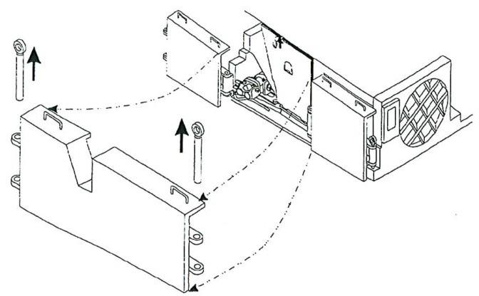
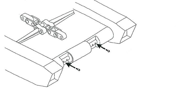
9. Remove the two rub rail pins that secure the tram rub rail to the two rub rail sections adjacent to it and remove the tram rub rail to expose the tram case.
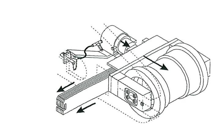
10. Remove the tram case (see Tram case removal and installation procedure in this chapter).
11. Remove the plug from the motor end of the reach gear case bottom and drain the lubricant from the gear case.
12. When the lubricant has been completely drained, replace the plug.
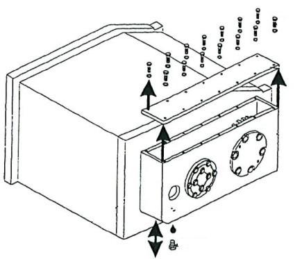
13. Remove the hex head cap screws and lock washers (Fig. 177) that secure the reach gear case cover to the gear case and remove the cover.
Fig. 177: Reach gear case cover removal
Hex head cap screws
Lock washers
Reach gear case cover
Rear side of tram case Drain plug Reach gear case
14. Locate the cap bearing carrier that secures the tram drive pinion inside the reach gear case.
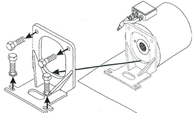
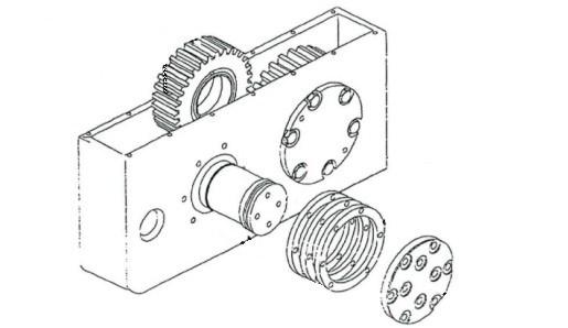
15. Using retaining ring pliers, remove the retaining ring located outside the cap bearing carrier on the tram drive pinion (Fig. 178).
16. Using the wire cutters, cut and remove the wire securing the cap bearing carrier cap screws in position.
17. Remove the four drilled head cap screws and lock washers that secure the cap bearing carrier to the tram case and remove the cap bearing carrier.
Fig. 178: Cap bearing carrier removal
Drilled head cap screws Cap bearing carrier
Retaining ring
Tram drive pinion
20. Remove the three steel shims and the bearing found under the shims (Fig. 179).
21. Carefully pull the tram drive pinion out of the reach gear case through the cap bearing carrier opening.
Fig. 179: Tram drive pinion removal
Bearing carrier opening
Cap bearing carrier
Tram drive pinion
Bearing cup and cone set Shims
22. Cut and remove the wire securing the idler shaft cap screws in position.
23. Remove the drilled hex head cap screws that secure the idler shaft cap to the tram case and remove the idler shaft and three steel shims located under the cap.
24. Carefully slide the idler shaft out of the reach gear case through the idler shaft cap opening.
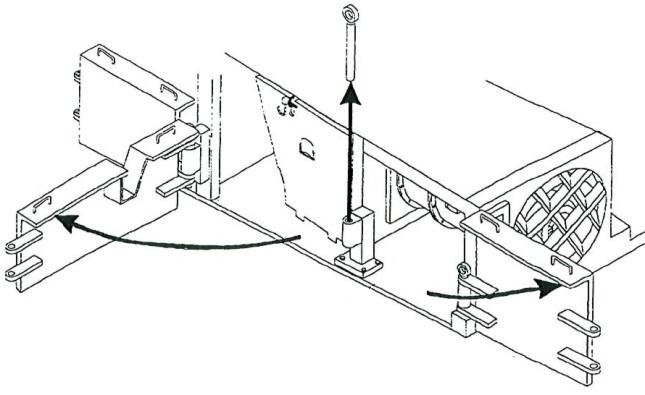
25. Remove the idler reach gear through the top opening of the reach gear case (Fig. 180).
26. Remove the bearing cup and cone sets from the center indentions of the idler reach gear.
Fig. 180: Idler reach gear and idler shaft removal
Rear side of tram case Idler reach gear Bearing cup and cone set
Reach gear case
Shims

Hex head cap
Idler shaft cap
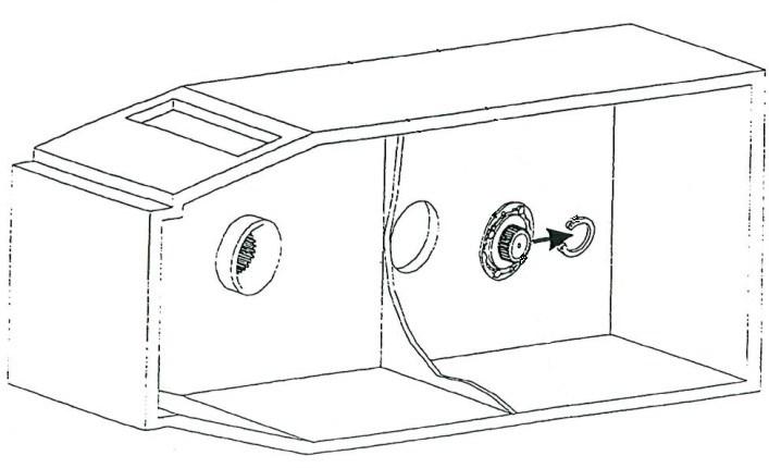
27. Remove the hex head cap screws and lock washers that secure the sprocket reach gear bearing cap to the reach gear case (Fig. 181).
28. Remove the bearing cap and the three steel shims under the cap.
29. Remove the bearing cone and cup set from the end of the splined sleeve.
30. Carefully slide the splined sleeve out of the sprocket reach gear.
31. Remove the sprocket reach gear through the top opening of the reach gear case.
Fig. 181: Sprocket reach gear removal
Sprocket reach gear
Splined sleeve
Shims
Reach gear case Bearing cup and cone set
Sprocket reach gear bearing cap Hex head cap
tram reach gear set installation
32. Remove the second splined sleeve bearing cone and cup set from the rear of the reach gear case, located behind the sprocket reach gear.
To install the tram reach gear set:
1. Insert one of the bearing cup and cone sets (cone side facing out) into the cut-out inside the reach gear case adjacent to the tram case sprocket (Fig. 182).
Fig. 182: Bearing cup and cone set installation
Bearing cup and cone set
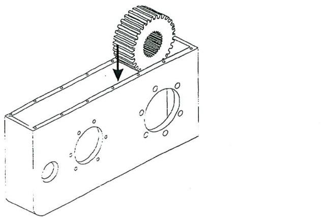
2. Insert the sprocket reach gear into the top of the reach gear case and position it against the bearing cup and cone set adjacent to the tram case sprocket (Fig. 183).
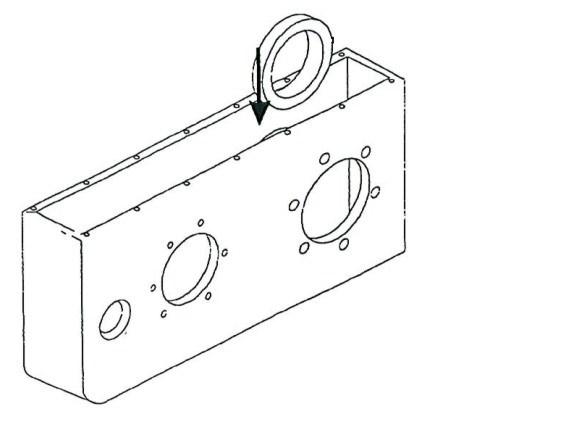
Fig. 183: Sprocket reach gear installation
Sprocket reach gear set
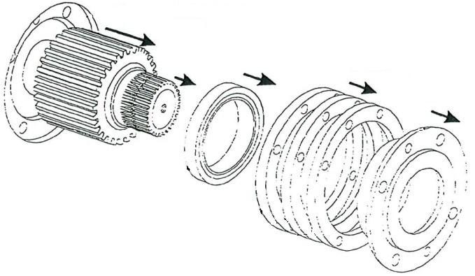
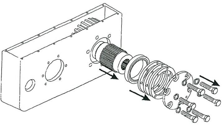
3. Insert the splined sleeve into the reach gear case (Fig. 184), through the sprocket reach gear and through the bearing cup and cone set until it is positioned against the tram sprocket.
4. Slide the second bearing cup and cone set (cup side facing out) onto the end of the splined sleeve.
5. Replace the three steel shims over the bearing set.
6. Replace the sprocket reach bearing cap.
7. Insert and tighten the hex head cap screws and lock washers to secure the sprocket reach gear bearing cap to the reach gear case.
Fig. 184: Splined sleeve and bearing cap installation
Sprocket reach gear
Splined sleeve
Shims
Reach gear case Bearing cup and cone set

Sprocket reach gear bearing cap Hex head cap screws
8. Insert two cup and cone bearing sets into the central cut-outs on either side of the idler reach gear (Fig. 185). The cone side of the bearing sets should face out of the gear on both sides.
9. Insert the idler reach gear through the top opening of the reach gear case and position it against the sprocket reach gear, ensuring that the gear teeth securely mesh.
10. Insert the idler shaft through the bearing sets in the idler reach gear until it is positioned against the tractor frame.
11. Replace the three steel shims over the idler shaft.
12. Replace the idler shaft cap.
Fig. 185: Idler reach gear and idler shaft installation
Rear side of tram case Idler reach gear Bearing cup and cone set
Reach gear case
Shims
Hex head cap screws
Idler shaft cap
13. Insert and tighten the ten drilled hex head cap screws to secure the idler shaft cap.
14. Insert the tram drive pinion through the cap bearing carrier opening (located on the inside of the tram case tram motor bay) into the reach gear case. Ensure that the teeth of the pinion securely mesh with the idler reach hear teeth.
15. Replace the pinion bearing.
16. Replace the three steel shims over the pinion bearing.
17. Replace the cap bearing carrier over the pinion end.
18 Insert and tighten the drilled hex head cap screws and lock washers to secure the cap bearing carrier to the tram case.
19. Install the retaining ring on the tram drive pinion.
20. Double check that the tram drive pinion, idler reach gear and sprocket reach gear teeth are properly meshed and the gears rotate smoothly.
21. Tighten the sprocket reach gear bearing cap cap screws to correct torque (see Torque tables in Chapter 6 of this manual).
22. Tighten the idler shaft cap cap screws to correct torque (see
Torque tables in Chapter 6 of this manual).
23. Lock wire the idler shaft cap cap screws to secure their positions.
24. Tighten the tram drive pinion cap bearing carrier cap screws to correct torque (see Torque tables in Chapter 6 of this manual).
25. Lock wire the tram drive pinion cap bearing carrier cap screws to secure their positions.
26. Replace the reach gear case cover onto the top of the reach gear case.
27. Insert and tighten fourteen hex head cap screws and lock washers to secure the reach gear case cover to the gear case.
28. Remove the plug from the sprocket side of the reach gear case cover.
29. Fill the reach gear case to the proper level with lubricant (Spec. 100 -14).
30. Replace the fill plug.
31. Replace the tram case into the tractor frame (see Tram case removal and installation procedure in this chapter).
IMPORTANT! The re-installation procedure for the tram case includes reinstallation of the primary and secondary planetary gears and the tram motor, and reconnection of the tram track.
32. Replace the tram rub rail between the two adjacent rub rails and secure it with the two rub rail pins.
33. Reconnect the trailing cable to energize the miner.
34. Raise the tractor frame by lowering the stabilizer and the gathering head and cutter head assemblies.
35. Carefully remove the support blocking from under the tractor frame.
36. Lower the tractor frame onto the floor by raising the stabilizer and the gathering head and cutter head assemblies.