7 minute read
Tram sprocket ..............................................................5

tram sprocket removal Tram sprocket removal and installation
Advertisement
To remove the tram sprocket:
1. Lower the conveyor tail section until it is level with the floor.
2. Raise the gathering head and cutter head and place a small stack of blocking under these two assemblies.
WARNING! You could be seriously injured or killed by falling loads. Observe the safe working load limits of all blocking devices.
3. Lower the gathering head and cutter head onto the blocking so that the front end of the miner lifts off the floor.
4. Extend the stabilizer completely so that the rear end of the miner lifts off the floor.
5. Place blocking in multiple locations under the miner tram track.
When the miner is lowered, the tram track should be secured between the blocking and the tractor frame.
WARNING! You could be seriously injured or killed by falling loads. Observe the safe working load limits of all blocking devices.
6. Raise the stabilizer and the gathering head and cutter head assemblies so the weight of the miner rests on the blocking.
7. Disconnect the trailing cable to de-energize the miner. Follow all
Federal and mine regulations for lockout/tagout.
WARNING! Follow all federal and mine lockout/tagout regulations. Failure to do so could result in machine damage or serious injury or death to personnel.
8. Double check the tractor frame support blocking now that the weight of the tractor frame is completely upon it.
9. Remove the two rub rail pins that secure the tram rub rail to the two rub rail sections adjacent to it and remove the tram rub rail to expose the tram case.
10. Remove the hex head cap screw and lock washer that secures the front rub rail to the tractor frame and open the cover.
11. Attach the grease gun to the fitting on the grease take-up cylinder (Fig. 186) and pump grease to extend the cylinder and remove pusher plate pressure on the idler shims.
12. Remove all the idler adjustment shims and store the shims in a safe place.
13. Open the pressure release valve for the front idler take-up jack and allow the cylinder to contract.
Fig. 186: Idler adjustment shim removal
Pressure release valve Idler take-up cylinder
Grease fitting
Idler adjustment shims
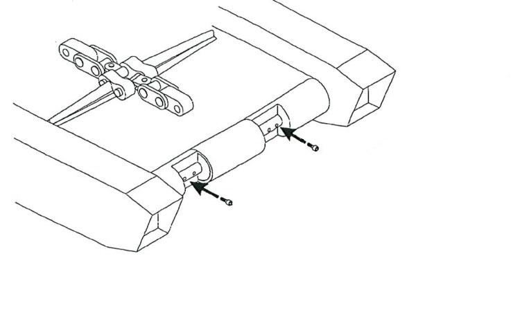
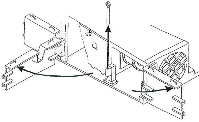
14. Locate a tram track link near the track entry opening at the bottom of the tram case (Fig. 187) and, using the hammer and punch, remove the two roll pins that secure the tram track pin between the links. Store the roll pins in a safe place.
15. Using the hammer and punch, remove the tram track pin to disconnect the links and separate the track. Store the track pin in a safe place.
Fig. 187: Tram track removal
Roll pins Separate track here
Tram track pin

16. Attach guide wires to the end of the tram track that passes through the tram case.
17. Connect the trailing cable to energize the miner.
18. Use the tram motor to slowly rotate the sprocket so that the end of the tram track that passes through the case is pulled up through the case and rolls off the sprocket.
19. Disconnect the trailing cable to de-energize the miner. Follow all
Federal and mine regulations for lockout/tagout.
WARNING! Follow all federal and mine lockout/tagout regulations. Failure to do so could result in machine damage or serious injury or death to personnel.
20. Pull on the tram track from the front of the miner (near the idler) so that the free end of the tram track is pulled clear of the tram case exit opening.
WARNING! Ensure that the end of the tram track is out of the tram case exit opening before attempting to remove the tram case from the tractor frame.
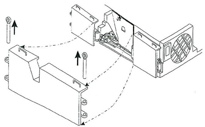
21. Remove the plug from the bottom of the cover and drain the lubricant from the gear case (Fig. 188).
22. Replace the oil drain plug in the gear cover.
23. Remove the Secondary planetary gear assembly (see Secondary planetary gear assembly removal and installation procedure in this chapter).
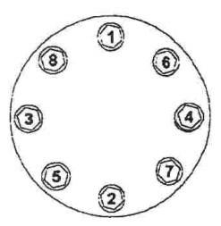
Fig. 188: Tram secondary planetary gear cover and drain plug
Tram secondary planetary gear cover
Socket head cap screws

Drain plug
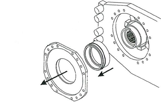
24. Remove the bearing carrier (Fig. 189).
25. Remove the bearing/seal sleeve assembly from the end of the sprocket.
Fig. 189: Sprocket bearing carrier removal
WARNING! The next step removes the sprocket from the tram case. The sprocket is extremely heavy. Be prepared to support its weight before removing it from the tram case.
Bearing/seal sleeve assembly
Sprocket bearing carrier Sprocket
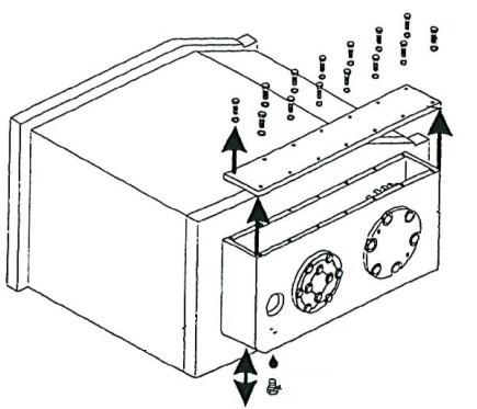
26. Remove the sprocket from the tram case (Fig. 190).
27. Remove the bearing/seal sleeve assembly from the rear of the sprocket bay of the tram case.
Fig. 190: Tram sprocket removal
Bearing/seal sleeve assembly
Sprocket Tram case

tram sprocket installation
To install the tram sprocket:

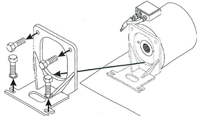
1. Install a spherical bearing into one of the bearing sleeves (Fig. 191).
2. Install the o-ring into the outside channel of the bearing sleeve.
IMPORTANT! When the bearing sleeve is inserted into position, the o-ring forms a seal between the sleeve and the piece that holds it.
3. Install a Duo-Cone seal into the seal sleeve (see Duo-cone seal installation notes in this chapter). The rubber side of the seal should face toward the sleeve; the metal ring of the seal should face outward.
Fig. 191: Bearing/seal sleeve assembly
Seal sleeve
Duo-cone seal Spherical bearing
Bearing sleeve O-ring
Metal ring Rubber seal
5. Insert and tighten the three set screw into the bearing sleeve to secure the seal sleeve in the bearing sleeve.
6. Insert the bearing/seal sleeve assembly into position at the rear of the sprocket bay of the tram case.
7. Install the two Duo-Cone seals into the channel in each end of the sprocket. The rubber side of the seals should face into the sprocket channel; the metal rings of the Duo-Cone seals should face outward.
8. Insert the end of the sprocket into the seal sleeve so that it seats into the spherical bearing. Push the sprocket until the metal rings of the Duo-Cone seals are securely against each other.
9. Install the other spherical bearing into the remaining bearing sleeve.
10. Install the o-ring into the outside channel of the bearing sleeve.
11. Install a Duo-Cone seal into the remaining seal sleeve. The rubber side of the seal should face toward the sleeve; the metal ring of the seal should be facing outward.
12. Insert the seal sleeve into the bearing sleeve.
13. Insert and tighten the three set screws into the bearing sleeve to secure the seal sleeve in position.
14. Slide the bearing/seal sleeve assembly onto the end of the sprocket. Push the sleeve assembly until the end of the sprocket seats into the spherical bearing and the metal rings of the Duo-Cone seals are securely against each other.
15. Replace the bearing carrier over the bearing sleeve and end of the bearing sleeve and end of the sprocket.
16. Install the Secondary planetary gear assembly (see the Secondary planetary gear assembly removal and installation procedure in this chapter).
17. While feeding the tram track from the front of the miner (near the idler), pull on the tram track guide wires until a link of the tram track engages the sprocket.
18. Connect the trailing cable to energize the miner.
WARNING! Stand clear of the miner when using the motor to pull the tram track through the tram case.
19. Use the tram motor to slowly rotate the sprocket and pull the tram track through the case until the end appears out the bottom.
WARNING! Double check that the links of the tram track are correctly seated onto the tram drive sprocket. Improper engagement of the tram track links onto the sprocket can cause serious mechanical damage.
20. Disconnect the trailing cable to de-energize the miner. Follow all
Federal and mine regulations for lockout/tagout.
WARNING! Follow all federal and mine lockout/tagout regulations. Failure to do so could result in machine damage or serious injury or death to personnel.
21. Remove the guide wires from the tram track.
22. Connect the two ends of the tram track and using the hammer and punch, insert the track pin to secure the two track links together.
23. Using the hammer and punch, insert the two roll pins into the track pin to secure the pin in the links.
24. Adjust the tram track tension (see Tram track adjustment procedure in the Adjustment procedures section of this chapter).
25. Close the front rub rail cover and replace the hex head cap screws and lock washers that secure the front rub rail to the tractor frame.
26. Replace the tram rub rail between the two adjacent rub rails and secure it with the two rub rail pins.
27. Connect the trailing cable to energize the miner.
28. Remove blocking.