2 minute read
Hydraulic pump ............................................................5


Hydraulic pump removal
Advertisement
1. Lower the conveyor tail section until it is level with the floor.
2. Lower the gathering head and cutter head assemblies until they rest on the floor.
3. Disconnect the trailing cable to de-energize the miner. Follow all
Federal and mine regulations for lockout/tagout.
WARNING! Follow all federal and mine lockout/tagout regulations. Failure to do so could result in machine damage or serious injury or death to personnel.
There are two alternative locations and instructions for the removal of the hydraulic pump: in front of the demister box or behind the operator’s case.
When located in front of the demister box:
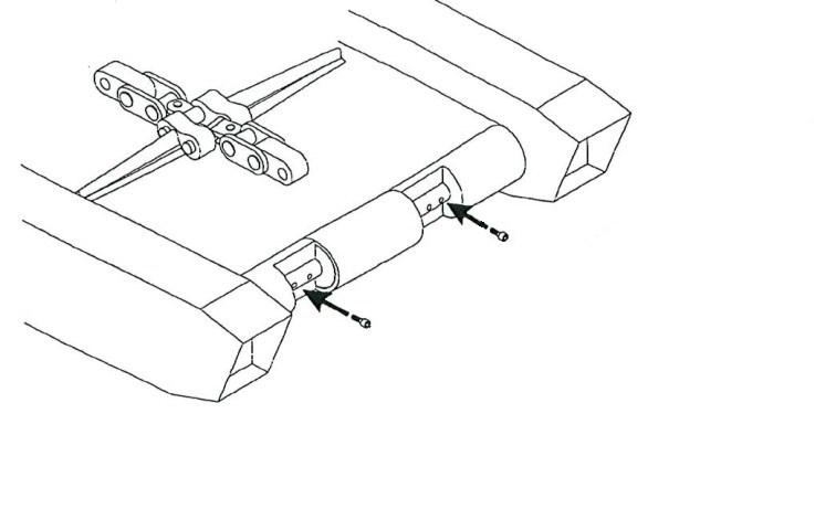
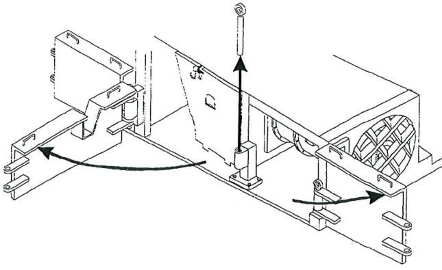
4. Locate the rub rail directly behind the tram case on the scrubber exhaust side of the miner (Fig. 200). Remove the two rub rail pins that secure the rub rail to the two rub rail sections adjacent to it and remove the rub rail.
Fig. 200: Pump located behind demister
Hydraulic pump
Rub rail Scrubber exhaust
5. Locate the hydraulic pump and motor assembly (Fig. 200).
6. Using the adjustable wrench, disconnect the inlet hose from the pump. Plug the hose end to keep it clean.
7. Using the adjustable wrench, disconnect the pilot and valve hoses from the pump fittings. Plug the hose ends to keep them clean.
8. Remove the hose fittings from the pump and store in a safe place.
9. Remove the two hex head cap screws and lock washers that secure the pump assembly to the motor assembly.
10. Carefully remove the pump assembly by sliding it out of the pump motor.
When located behind the operator’s case:
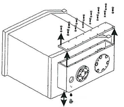
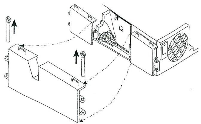
4. Locate the rub rail directly behind the tram case on the operator’s side of the miner. Remove the two rub rail pins that secure the rub rail to the two rub rail sections adjacent to it and remove the rub rail.
5. Swing the operator’s case outward and locate the hydraulic pump and motor assembly.
6. Using the adjustable wrench, disconnect the inlet hose from the pump. Plug the hose end to keep it clean.
7. Using the adjustable wrench, disconnect the pilot and valve hoses from the pump fittings. Plug the hose ends to keep them clean.
Hydraulic pump installation
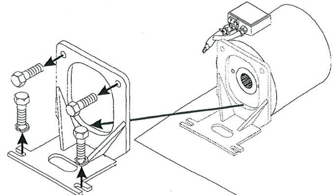
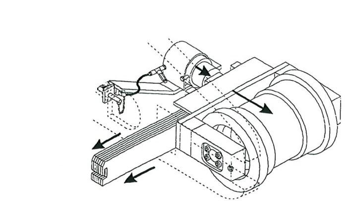
1. Slide the pump assembly into the pump motor (Fig. 201).
2. Insert and tighten, hex head cap screws and lock washers to secure the pump assembly to the motor.
Fig. 201: Hydraulic pump installation
Motor
Hex head cap screw Pump
Lock washer (2)

3. Insert the hydraulic hose fittings into the pump assembly and tighten.
4. Attach and tighten the exit pilot and valve hoses to the pump fittings.
5. Attach the inlet hose to the pump.
6. Replace the rub rail between the two adjacent rub rails and secure it with the two rub rail pins.
7. Check the hydraulic fluid level.
8. Jog pump motor on and off a few times to prime the pump before starting.