52 minute read
MAINTENANCE SAFETY


Instructions are necessary before operating or servicing machine. Read and understand the Operation & Maintenance Manual, Operator’s Handbook and signs (decals) on machine. Follow warnings and instructions in the manuals when making repairs, adjustments or servicing. Check for correct function after adjustments, repairs or service. Untrained operators and failure to follow instructions can cause injury or death.
W-2003-0807
Safety Alert Symbol: This symbol with a warning statement, means: “Warning, be alert! Your safety is involved!” Carefully read the message that follows.
Never service the Bobcat Compact Excavator without instructions.

Use the correct procedure to lift and support the excavator.
Cleaning and maintenance are required daily.
Have good ventilation when welding or grinding painted parts. Wear dust mask when grinding painted parts. Toxic dust and gas can be produced.
Vent exhaust to outside when engine must be run for service. Exhaust system must be tightly sealed. Exhaust fumes can kill without warning.
Always lower the bucket and blade to the ground before doing any maintenance. Never modify equipment or add attachments not approved by Bobcat Company.
Stop, cool and clean engine of flammable materials before checking fluids. Never service or adjust machine with the engine running unless instructed to do so in the manual.
Avoid contact with leaking hydraulic fluid or diesel fuel under pressure. It can penetrate the skin or eyes.
Never fill fuel tank with engine running, while smoking, or when near open flame.
Keep body, jewelry and clothing away from moving parts, electrical contact, hot parts and exhaust. Wear eye protection to guard from battery acid, compressed springs, fluids under pressure and flying debris when engines are running or tools are used. Use eye protections approved for type of welding. Keep tailgate closed except for service. Close and latch tailgate before operating the excavator.
Lead-acid batteries produce flammable and explosive gases. Keep arcs, sparks, flames and lighted tobacco away from batteries.
Batteries contain acid which burns eyes or skin on contact. Wear protective clothing. If acid contacts body, flush well with water. For eye contact flush well and get immediate medical attention.
Maintenance procedures which are given in the Operation & Maintenance Manual can be performed by the owner/ operator without any specific technical training. Maintenance procedures which are not in the Operation & Maintenance Manual must be performed ONLY BY QUALIFIED BOBCAT SERVICE PERSONNEL. Always use genuine Bobcat replacement parts. The Service Safety Training Course is available from your Bobcat dealer.
MSW38-0409

Service Schedule
Maintenance Intervals
Maintenance work must be done at regular intervals. Failure to do so will result in excessive wear and early failures.
The service schedule is a guide for correct maintenance of the Bobcat excavator.
Warning
Avoid Injury Or Death
Instructions are necessary before operating or servicing machine. Read and understand the Operation & Maintenance Manual, Operator’s Handbook and signs (decals) on machine. Follow warnings and instructions in the manuals when making repairs, adjustments or servicing. Check for correct function after adjustments, repairs or service. Untrained operators and failure to follow instructions can cause injury or death.
W-2003-0807
Every 10 Hours (Before Starting The Excavator)
• Engine Oil - Check level and add as needed.
• Engine Air Filters and Air System - Check display panel. Service only when required. Check for leaks and damaged components.
• Engine Cooling System - Check coolant level COLD and add premixed coolant as needed.
• Hydraulic Fluid - Check fluid level and add as needed.
• Fuel Filter - Drain water and sediment from filter.
• Seat Belt, Seat Belt Retractors, Seat Belt Mounting hardware, Control Console Lockout - Check the condition of seat belt and mounting hardware. Clean or replace seat belt retractors as needed. Check the control console lockout lever for proper operation. Clean dirt and debris from moving parts.
• Motion Alarm - Check for proper function.
• Operator Canopy / Cab - Check the canopy / cab condition and mounting hardware.
• Operator Cab and HVAC Filters - Clean filters as needed.
• Indicators and Lights - Check for correct operation of all indicators and lights.
• Safety Signs - Check for damaged signs (decals). Replace any signs that are damaged.
• Track Tension - Check tension and adjust as needed.
• Pivot Points - Grease all machinery pivot points. Grease clamp and angle blade (if equipped).
• X-Change / Attachment Coupler - Check for damage or loose parts (if equipped).
Every 50 Hours
• Swing Bearing - Grease swing bearing and swing pinion. Service every 10 hours when operating in water.
• Battery - Check cables, connections, and electrolyte level; add distilled water as needed.
• Fuel Tank - Drain water and sediment from fuel tank and fuel filter.
Every 250 Hours Or Every 12 Months
• Travel Motors (Final Drive) - Service at first 50 hours, then as scheduled. Check fluid level and add as needed.
SS EXC E32 - E55 iT4 T4-K-0815
SERVICE SCHEDULE (CONT’D)
Maintenance Intervals (Cont’d)
Every 500 Hours Or Every 12 Months
• Engine Oil and Filter - Service at first 50 hours, then as scheduled. Replace oil and filter.
• Fuel Filter – Replace filter element.
• Cooling System - Clean debris from radiator, fuel cooler, hydraulic fluid cooler, air conditioning condenser (if equipped).
• Hydraulic Filter, Case Drain Filter and Hydraulic Reservoir Breather Cap - Service at first 50 hours, then as scheduled. Replace the hydraulic filter, case drain filter and the reservoir breather cap.
• Drive Belts (Alternator) (Air Conditioning - If Equipped) - Check condition. Replace as needed. Service at first 50 hours, then as scheduled.
• Alternator and Starter - Service at first 50 hours, then as scheduled. Check connections.
• HVAC - Clean housing and coils.
Every 1000 Hours Or Every 12 Months
• Swing Cylinder Base End - Grease swing cylinder base end grease fitting.
• Hydraulic Fluid and Filters - Replace hydraulic fluid and filters.
• Travel Motors (Final Drive) - Service at first 50 hours, then as scheduled. Replace fluid.
• Engine Valves - Adjust the engine valve clearance.
Every 24 Months
• Coolant - Replace the coolant.
SERVICE SCHEDULE (CONT’D)
Inspection Checkbook
Regularly scheduled maintenance is essential to continuous operation and operating safety. The life expectancy of your machine depends on proper and meticulous care.
The Inspection Checkbook contains the following information:
Doosan Benelux S.A. Warranty Conditions
Protection Plus Extended Warranty Conditions
General Parts Policy
General Information
First Inspection
Scheduled Services
Identification
Authorised Identification
Lubricants and Fluids Table Service Parts Chart
Your local dealer can order the Inspection Checkbook. Part number: 4420310.
Control Console Lockouts
Inspection And Maintenance
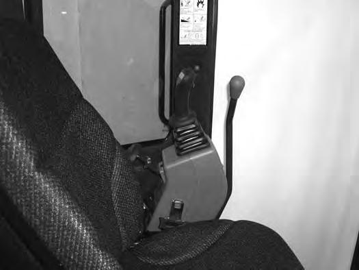
Figure 257
When the left console is raised [Figure 257], the hydraulic control levers (joysticks) and traction system must not function.
Sit in the operator's seat, fasten the seat belt and start the engine.
Raise the left console [Figure 257]
Move the joystick control levers. There should be no movement of the boom, arm, slew or bucket.
Move the steering control levers. There should be no movement of the excavator tracks.
Service the system if these controls do not deactivate when the left control console is raised. (See your Bobcat dealer for service.)
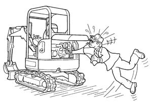
Failure to properly inspect and maintain the seat belt can cause lack of operator restraint resulting in serious injury or death.
W-2466-0703
Check the seat belt daily for correct function.
Inspect the seat belt system thoroughly at least once each year or more often if the machine is exposed to severe environmental conditions or applications.
Any seat belt system that shows cuts, fraying, extreme or unusual wear, significant discolourations due to ultraviolet UV exposure, dusty / dirty conditions, abrasion to the seat belt webbing, or damage to the buckle, latch plate, retractor (if equipped), hardware or any other obvious problem should be replaced immediately.

The items below are referenced in [Figure 258]
1.Check the webbing. If the system is equipped with a retractor, pull the webbing completely out and inspect the full length of the webbing. Look for cuts, wear, fraying, dirt and stiffness.
2.Check the buckle and latch for correct operation. Make sure latch plate is not excessively worn, deformed or buckle is not damaged or casing broken.
3.Check the retractor web storage device (if equipped) by extending webbing to determine if it looks correct and that it spools out and retracts webbing correctly.
4.Check webbing in areas exposed to ultraviolet (UV) rays from the sun or extreme dust or dirt. If the original colour of the webbing in these areas is extremely faded and / or the webbing is packed with dirt, the webbing strength may have deteriorated.
See your Bobcat dealer for seat belt system replacement par ts for your machine.
MOTION ALARM SYSTEM Description
This excavator may be equipped with a motion alarm system. The motion alarm will sound when the operator moves the travel control levers in either the forward or reverse direction. Slight movement of the steering levers in either the forward or reverse direction is required with hydraulic components before the motion alarm will sound.
Inspecting
Warning
Avoid Injury Or Death
When an engine is running in an enclosed area, fresh air must be added to avoid concentration of exhaust fumes. If the engine is stationary, vent the exhaust outside. Exhaust fumes contain odorless, invisible gases which can kill without warning.
Sit in the operator’s seat and fasten the seat belt. Start the engine. (See PRE-STARTING PROCEDURE on Page 67.)
Move the travel control levers (one lever at a time) in the forward direction. The motion alarm must sound. Move the travel control levers (one lever at a time) in the reverse direction. The motion alarm must sound.
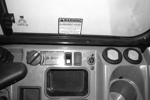
Inspect for damaged or missing motion alarm decal (Item 1) [Figure 259] (cab machine) or (Item 1) [Figure 260] (canopy machine). Replace if required.


NOTE:The excavator will need to be moved slightly in both the forward and reverse direction to test the motion alarm. Keep all bystanders away from machine during test.
Slightly move both travel control levers in the forward direction (until the machine is slowly moving forward) and then press the motion alarm cancel switch (Item 1) [Figure 261]. The motion alarm will shut off. With the machine still moving forward, move one of the levers to the NEUTRAL position, the motion alarm must sound.
Slightly move both travel control levers in the reverse direction (until the machine is slowly moving backward) and then press the motion alarm cancel switch (Item 1) [Figure 261] (the switch icon will be illuminated when the motion alarm is deactivated). The motion alar m will shut off. With the machine still moving backward, move one of the levers to the NEUTRAL position, the motion alarm must sound.
Return both levers to NEUTRAL and turn excavator key to OFF position. Exit the excavator. (See STOPPING THE ENGINE AND LEAVING THE EXCAVATOR on Page 75.)
MOTION ALARM SYSTEM (CONT’D)
Inspecting (Cont’d)
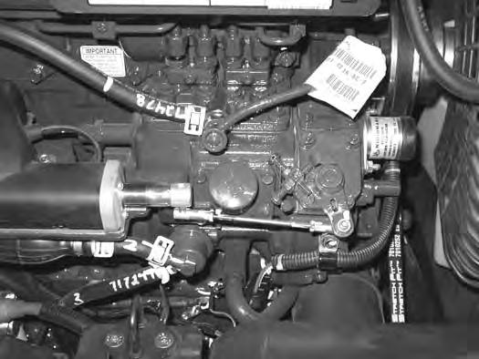
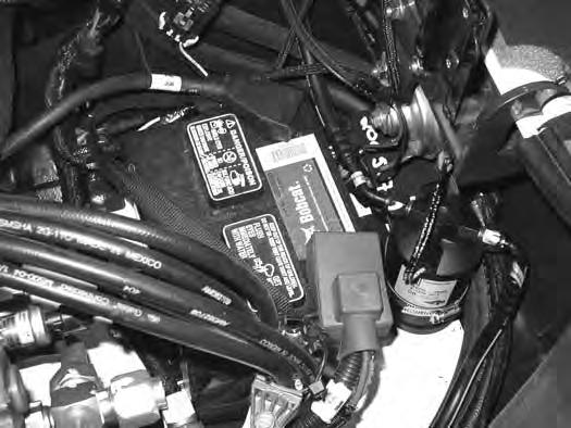
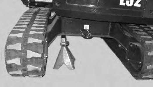
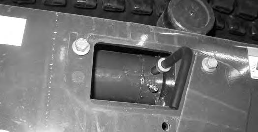
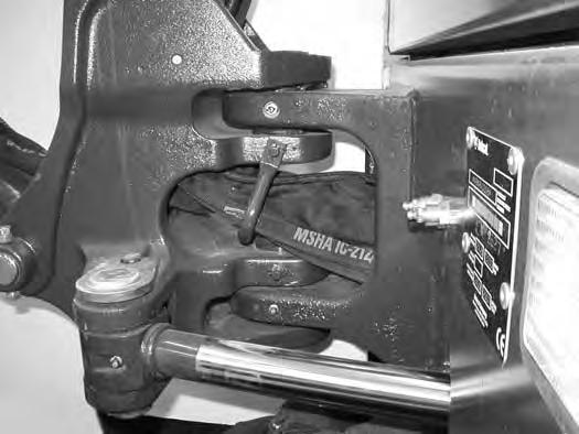
The motion alarm is mounted to the bottom rear of the excavator. (To the front of the engine oil pan.)
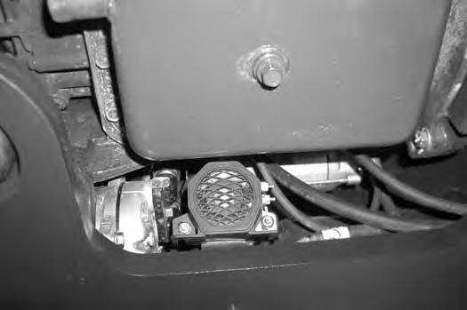
Figure 262
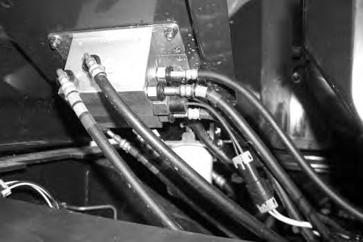
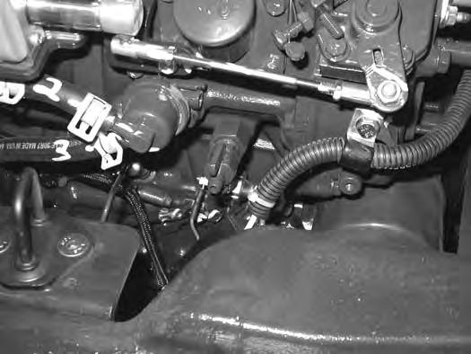
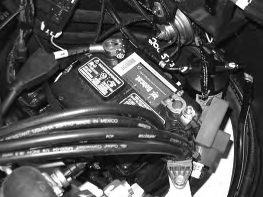
Inspect the motion alarm electrical connections and wire har ness (Item 1) [Figure 262], wire harness (Item 1) [Figure 263] and motion alarm switch (Item 2) [Figure 263] for tightness and damage. Repair or replace any damaged components.
If the motion alarm switch requires service, see the following information.
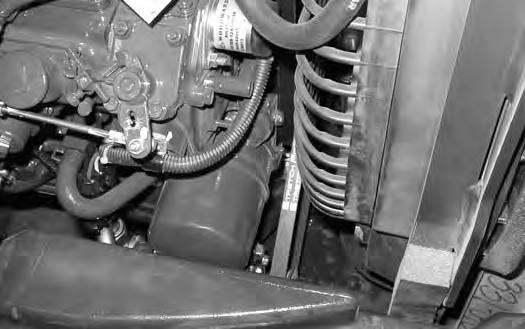
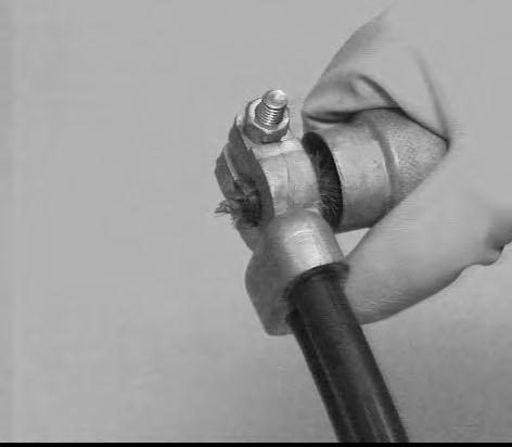
Adjusting Switch Position
Figure 263
The switch (Item 2) [Figure 263] is non-adjustable. It must be fully installed into the travel control valve housings and tightened. Tighten the switch to 18 - 20 N•m (13 - 15 ft-lb).
Inspect the motion alarm system for proper function after switch replacement.
Warning
This machine is equipped with a motion alarm. ALARM MUST SOUND! when operating forward or backward.
Failure to maintain a clear view in the direction of travel could result in serious injury or death.
The operator is responsible for the safe operation of this machine.
TAILGATE

Opening And Closing
Warning
Avoid Injury Or Death
Never service or adjust the machine when the engine is running unless instructed to do so in the manual.
Warning
Keep the rear door closed when operating the machine. Failure to do so could seriously injure a bystander.
Adjusting The Latch
Pull the latch (Item 1) [Figure 264] and open the tailgate. Push firmly to close the tailgate.
NOTE: The tailgate can be locked using the start key.
Open the tailgate to access the right side cover latch (Item 1) [Figure 266]


Pull the latch handle (Item 1) [Figure 266] out until the right side cover is unlatched.
Raise the right side cover and rotate forward until it is held open by the retainer (Item 1) [Figure 267]
To close the right side cover, lift up on the retainer (Item 1) [Figure 267] while raising the right side cover. Rotate the cover back until it is in the fully closed position. Secure the right side cover with the latch (Item 1) [Figure 266]
CAB FILTERS Cleaning And Maintenance
The recirculation filter and the fresh air filter must be cleaned regularly. (See SERVICE SCHEDULE on Page 145.)
The recirculation filter is located to the right of the operator seat and the fresh air filter is located under the right side cover.

Recirculation Filter
Figure 268
The recirculation filter (Item 1) [Figure 268] is located to the right of the operator’s seat.
Figure 269
Pull up on the filter (Item 1) [Figure 269] until removed from the housing.
Shake the filter or use low pressure air to clean the filter. Replace the filter when very dirty or if damaged.
Installation: Position the bottom of the filter (Item 1) [Figure 269] into the housing and slowly push the filter down fully.
Fresh Air Filter
Figure 270
The fresh air filter is located under the right side cover. Open the right side cover. (See RIGHT SIDE COVER on Page 152.)

Pull out on the tab (Item 1) and remove the cover (Item 2) [Figure 270]
Pull the filter (Item 1) [Figure 271] out of the housing.
Shake the filter or use low pressure air to clean the filter. Do not use solvents. Replace the filter when very dirty or damaged.
Installation: Position the filter (Item 1) [Figure 269] into the housing and slowly push the filter in fully.
Place the bottom tabs of the filter cover (Item 2) into the frame and push the top in until the tab (Item 1) [Figure 270] locks to the frame.
HEATING, VENTILATION AND AIR CONDITIONING (HVAC)
Cleaning And Maintenance
The inside of the HVAC housing needs to be cleaned regularly. Dust will accumulate over time inside the housing. A dusty heater and evaporator coil will reduce heating and cooling efficiency. (See SERVICE SCHEDULE on Page 145.)
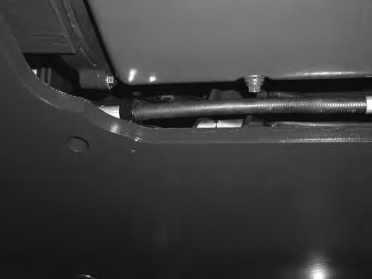
The HVAC housing is located to the right of the operator seat.
After the housing has been cleaned and flushed, remove the jackstands and raise the blade so the front of the excavator is flat on the ground. Stop the engine.

There are three rubber drain valves that allow condensation to drain from the housing during normal air conditioning usage. These drain valve can get clogged with dirt and should be cleaned at the same time the housing is cleaned.
Two of the drain valve can be accessed from the right side cover (the drain valves are located below the HVAC housing on the right side) and one of the valves is located below the left rear corner of the HVAC housing and will be accessed by removing the centre floorplate.
Pinch the three rubber drain valves on the flat sides to open the valves and allow dirt and moisture to exit from the end of the valves.
Reinstall the centre floorplate and close the right side cover.
Remove the floor mat.
Pull back on the two latches (Item 1) [Figure 272] and remove the HVAC side cover.
To allow water to drain from the HVAC housing during the cleaning process, it is recommended to rotate the upperstructure 90° to the right. Then using the blade, raise the front of the excavator to allow water to run out of the housing. Use jackstands to support the front of the undercarriage.


NOTE: The floor mat needs to be removed to allow easier access for installing the HVAC side cover.
Three tabs (Item 1) are on the bottom of the HVAC housing that the side cover retainers (Item 2) [Figure 274] fit into.
Use a lower pressure air or a low pressure water stream to remove debris and to clean the coils (Item 1) [Figure 273]
Position the side cover on the tabs and starting with the front edge of the side cover, position it into the front of the HVAC housing. Press on the front of the cover to secure the front latch (Item 1) [Figure 272]. Then press in on the top edge of the side cover and work back to the rear of the cover and secure the rear latch.
Air Cleaner Service
See the SERVICE SCHEDULE for the correct service interval. (See SERVICE SCHEDULE on Page 145.)
Daily Check
The air cleaner is located in the engine compartment. Open the tailgate to access the air cleaner for service. (See TAILGATE on Page 151.)
Check the condition indicator (Item 1) [Figure 275]. If the red ring shows in the condition indicator, the filter needs to be replaced.
Replace the inner filter every third time the outer filter is replaced or as indicated.

Replacing Filter Elements
Outer Filter
Figure 276
Release the three fasteners (Item 1) [Figure 276]
Remove and clean the dust cup (Item 2) [Figure 276].
Pull the outer filter (Item 1) [Figure 277] from the air cleaner housing.
Check the housing for damage.
Clean the housing and the seal surface. DO NOT use compressed air.
Install a new filter.
278
Install the dust cup (Item 1) and engage the three fasteners (Item 2) [Figure 278]

Check the air intake hose and the air cleaner housing for damage. Make sure all connections are tight.
After the outer filter has been replaced, press the button (Item 1) [Figure 275] on the end of the condition indicator and start the engine. Run at full rpm, then reduce engine speed and stop the engine. If the red ring (Item 2) [Figure 275] shows in the condition indicator, replace the inner filter.

AIR CLEANER SERVICE (CONT’D)
Replacing Filter Elements (Cont’d)
Inner Filter
Only replace the inner filter under the following conditions:
• Replace the inner filter every third time the outer filter is replaced.

•After the outer filter has been replaced, press the button (Item 2) [Figure 275] on the end of the condition indicator. Start the engine. Run the engine at full rpm, then reduce engine speed. Stop the engine. If the red ring shows in the condition indicator, replace the inner filter.
Remove the dust cup, outer filter and inner filter (Item 1) [Figure 279]
NOTE: Make sure all sealing surfaces are free of dirt and debris.
Install the new inner filter.
Install the outer filter and the dust cup.
Press the button on the condition indicator to remove the red ring.
Close the tailgate.
Fuel System
Fuel Specifications
NOTE: Contact your local fuel supplier to receive recommendations for your region.
At a minimum, low sulfur diesel fuel must be used in this machine. Low sulfur is defined as 500 mg/kg (500 ppm) sulfur maximum.
Ultra low sulfur diesel fuel may also be used in this machine. Ultra low sulfur is defined as 15 mg/kg (15 ppm) sulfur maximum.
U.S. Standard (ASTM D975)
Use only clean, high quality diesel fuel, Grade Number 2-D or Grade Number 1-D.
The following is one suggested blending guideline that should prevent fuel gelling during cold temperatures:
Biodiesel Blend Fuel
Biodiesel blend fuel has unique qualities that should be considered before using in this machine:
•Cold weather conditions can lead to plugged fuel system components and hard starting.
•Biodiesel blend fuel is an excellent medium for microbial growth and contamination which can cause corrosion and plugging of fuel system components.
•Use of biodiesel blend fuel may result in premature failure of fuel system components, such as plugged fuel filters and deteriorated fuel lines.
•Shorter maintenance intervals may be required, such as cleaning the fuel system and replacing fuel filters and fuel lines.
•Using biodiesel blended fuels containing more than five percent biodiesel can affect engine life and cause deterioration of hoses, tubelines, injectors, injector pump and seals.
Apply the following guidelines if biodiesel blend fuel is used:
NOTE:Biodiesel blend fuel may also be used in this machine. Biodiesel blend fuel must contain no more than five percent biodiesel mixed with ultra low sulfur petroleum based diesel. This biodiesel blend fuel is commonly marketed as B5 blended diesel fuel. B5 blended diesel fuel must meet ASTM specifications.
E.U. Standard (EN590)
Use only clean, high quality diesel fuel that meets the specifications listed below:
•Low sulfur diesel fuel defined as 500 mg/kg (500 ppm) sulfur maximum
• Diesel fuel with cetane number of 51.0 and above. Clean, high quality diesel fuel that meets the EN590 specification may also be used.
NOTE:Biodiesel blend fuel may also be used in this machine. Biodiesel blend fuel must contain no more than seven percent biodiesel mixed with ultra low sulfur petroleum based diesel. This biodiesel blend fuel is commonly marketed as B7 blended diesel fuel. B7 blended diesel fuel must meet EN590 specifications.
•Ensure the fuel tank is as full as possible at all times to prevent moisture from collecting in the fuel tank.
•Ensure that the fuel tank cap is securely tightened.
•Biodiesel blend fuel can damage painted surfaces, remove all spilled fuel from painted surfaces immediately.
•Drain all water from the fuel filter daily before operating the machine.
•Do not exceed engine oil change interval. Extended oil change intervals can cause engine damage.
•Before vehicle storage; drain the fuel tank, refill with 100% petroleum diesel fuel, add fuel stabiliser and run the engine for at least 30 minutes.
NOTE:Biodiesel blend fuel does not have long term stability and should not be stored for more than three months.
FUEL SYSTEM (CONT’D)
Filling The Fuel Tank
Warning
AVOID INJURY OR DEATH
Stop and cool the engine before adding fuel. NO SMOKING! Failure to obey warnings can cause an explosion or fire.
W-2063-0807
Warning
AVOID INJURY OR DEATH
Always clean up spilled fuel or oil. Keep heat, flames, sparks or lighted tobacco away from fuel and oil. Failure to use care around combustibles can cause explosion or fire.
W-2103-0508
The fuel cap uses the start key to unlock the fuel cap.
Remove the fuel fill cap (Item 1) [Figure 280].
Use a clean, approved safety container to add fuel. Add fuel only in an area that has a free movement of air and no flames or sparks. NO SMOKING!
Install and tighten the fuel fill cap.

Clean up any spilled fuel.
See the SERVICE SCHEDULE for the service interval when to remove water from or replace the fuel filter. (See SERVICE SCHEDULE on Page 145.)
FUEL SYSTEM (CONT’D)
Fuel Filters
Removing Water
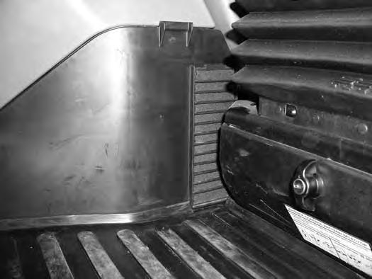
Open the tailgate. (See TAILGATE on Page 151.)
Draining The Fuel Tank
See the SERVICE SCHEDULE for the correct service interval. (See SERVICE SCHEDULE on Page 145.)
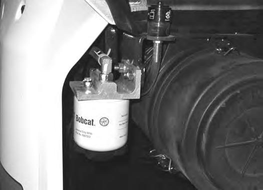
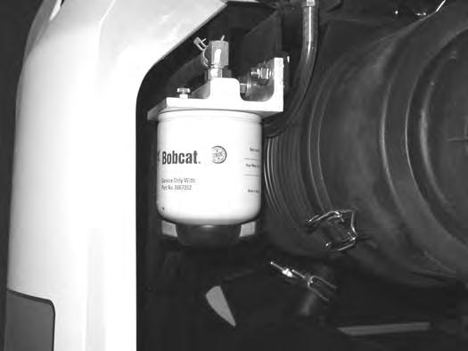
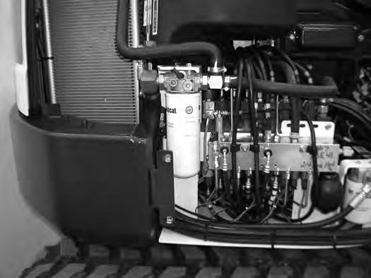
Loosen the drain (Item 1) [Figure 281] at the bottom of the filter to drain water from the filter into a container.
Clean up any spilled fuel.
Replacing Elements
Remove the filter (Item 2) [Figure 281]
Clean the area around the filter housing. Put clean oil on the seal of the new filter. Install the fuel filter and hand tighten.
Remove the air from the fuel system. (See Removing Air From The Fuel System on Page 160.)
Warning
AVOID INJURY OR DEATH
Diesel fuel or hydraulic fluid under pressure can penetrate skin or eyes, causing serious injury or death. Fluid leaks under pressure may not be visible. Use a piece of cardboard or wood to find leaks. Do not use your bare hand. Wear safety goggles. If fluid enters skin or eyes, get immediate medical attention from a doctor familiar with this injury.
W-2072-EN-0909
Squeeze the hand pump (priming bulb) (Item 1) [Figure 283] to start the fuel siphoning from the fuel tank.
Drain the fuel into the container.
Reuse, recycle or dispose of fuel in an environmentally safe manner.
Reinstall the hose (Item 1) [Figure 282] after the fuel is removed from fuel tank.
FUEL SYSTEM (CONT’D)
Removing Air From The Fuel System
After replacing the fuel filter or when the fuel tank has run out of fuel, air must be removed from the fuel system before starting the engine.
Warning
Avoid Injury Or Death
Diesel fuel or hydraulic fluid under pressure can penetrate skin or eyes, causing serious injury or death. Fluid leaks under pressure may not be visible. Use a piece of cardboard or wood to find leaks. Do not use your bare hand. Wear safety goggles. If fluid enters skin or eyes, get immediate medical attention from a doctor familiar with this injury.
Open the tailgate. (See TAILGATE on Page 151.)
Open the fuel filter vent (Item 1) [Figure 284] and operate the hand pump (priming bulb) (Item 1) [Figure 285] until the fuel flows from the vent with no air bubbles.
Close the vent (Item 1) [Figure 284]
Clean up any spilled fuel.
Start the engine. It may be necessary to open the vent (Item 2) [Figure 285] (at the fuel injection pump) briefly until the engine runs smoothly.
Engine Lubrication System

Checking And Adding Engine Oil
Check the engine oil after every 8 - 10 hours of operation and before starting the engine. (See SERVICE SCHEDULE on Page 145.)
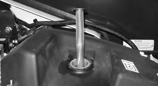
Figure 286
Open the tailgate. (See TAILGATE on Page 151.)
Remove the dipstick (Item 1) [Figure 286]
Keep the oil level between the marks on the dipstick.
Use a good quality motor oil that meets the correct API Ser vice Classification.
Engine Oil Chart
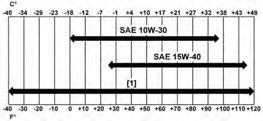
Figure 287
ENGINE OIL RECOMMENDED SAE VISCOSITY NUMBER (LUBRICATION OILS FOR DIESEL ENGINE CRANKCASE)
TEMPERATURE RANGE ANTICIPATED BEFORE NEXT OIL CHANGE (DIESEL ENGINES MUST USE API CLASSIFICATION CJ-4 OR BETTER, OR ACEA E9 OR BETTER)
[1] Bobcat Synthetic Oil – 5W-40
Bobcat engine oils are recommended for use in this machine. If Bobcat engine oil is not available, use a good quality engine oil that meets API Service Classification of CJ-4 or better, or ACEA E9 or better [Figure 287]
Warning
AVOID INJURY OR DEATH
Always clean up spilled fuel or oil. Keep heat, flames, sparks or lighted tobacco away from fuel and oil. Failure to use care around combustibles can cause explosion or fire.
ENGINE LUBRICATION SYSTEM (CONT’D)
Removing And Replacing Oil And Filter
See the SERVICE SCHEDULE for the service interval for replacing the engine oil and filter. (See SERVICE SCHEDULE on Page 145.)
Run the engine until it is at operating temperature. Stop the engine.
Open the tailgate. (See TAILGATE on Page 151.)
Figure 290
If equipped with the optional air deflector, remove the four bolts and the air deflector to access the drain hose (Item 1) [Figure 288]
Remove the drain hose (Item 1) from the storage clamp (Item 2) [Figure 288]
Figure 289
Place a container under the excavator. Remove the drain plug (Item 1) [Figure 289] from the drain hose.
Recycle or dispose of used oil in an environmentally safe manner.
Remove the oil filter (Item 1) [Figure 290] and clean the filter housing surface.
Use a genuine Bobcat replacement filter. Put clean oil on the filter gasket. Install the filter and hand tighten.
Install and tighten the drain plug (Item 1) [Figure 289]
Put the drain hose (Item 1) back into the storage clamp (Item 2) [Figure 288]
Figure 291
Remove the fill cap (Item 1) [Figure 291]
Put oil in the engine. (See ENGINE LUBRICATION SYSTEM on Page 161.) and (See Capacities on Page 220.)
Install the fill cap (Item 1) [Figure 291]
Start the engine and let it run for several minutes.
Stop the engine. Check for leaks at the oil drain plug and the oil filter. Check the oil level.
Add oil as needed if it is not at the top mark on the dipstick.

Engine Cooling System
Check the cooling system every day to prevent over-heating, loss of performance or engine damage. (See SERVICE SCHEDULE on Page 145.)
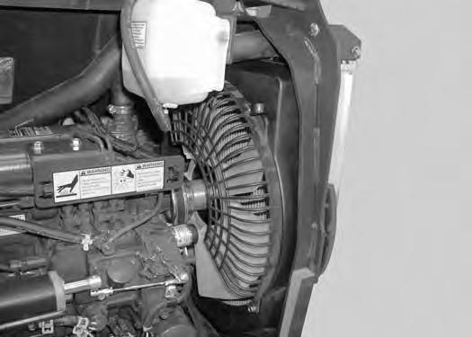
Cleaning
Open the right side cover. (See RIGHT SIDE COVER on Page 152.)
NOTE:Allow the cooling system and engine to cool before servicing or cleaning the cooling system.
Loosen the knob (Item 1) [Figure 292]. Slide the knob towards the rear of the machine.
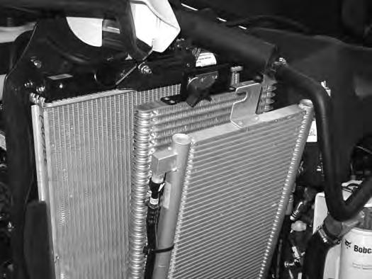
Use air pressure or water pressure to clean the radiator (Item 1), oil cooler (Item 2) and condenser (Item 3) [Figure 294] (if equipped). Be careful not to damage fins when cleaning.
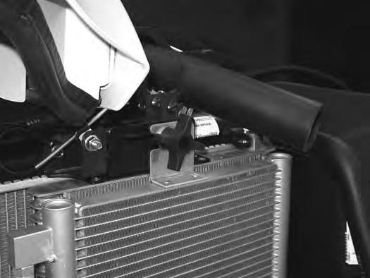
Position the knob (Item 1) so it fits into the radiator mount (Item 3) and the condenser mount (Item 2) [Figure 293] (if equipped).
Slide the knob (Item 1) [Figure 292] toward the front of the machine until it is fully seated in the slots of the mounting brackets. Tighten the knob (Item 1) [Figure 292]. Be careful not to damage fins.
Slide the knob (Item 1) out of the condenser mount (Item 2) (if equipped) and the radiator mounting bracket (Item 3) [Figure 293]. Be careful not to damage fins.
ENGINE COOLING SYSTEM (CONT’D)
Checking Level
Warning
AVOID BURNS
Do not remove radiator cap when the engine is hot. You can be seriously burned.
W-2070-1203
Warning
AVOID INJURY OR DEATH
Wear safety glasses to prevent eye injury when any of the following conditions exist:
•When fluids are under pressure.
•Flying debris or loose material is present.
•Engine is running.
•Tools are being used.
W-2019-0907
Open the tailgate. (See TAILGATE on Page 151.)
Figure 295
Important
AVOID ENGINE DAMAGE
Always use the correct ratio of water to antifreeze.
Too much antifreeze reduces cooling system efficiency and may cause serious premature engine damage.
Too little antifreeze reduces the additives which protect the internal engine components; reduces the boiling point and freeze protection of the system.
Always add a premixed solution. Adding full strength concentrated coolant can cause serious premature engine damage.

I-2124-0497
Check the coolant level in the coolant recovery tank (Item 1) [Figure 295]
The coolant level must be between the MIN and MAX marks on the coolant recovery tank when the engine is cold.
NOTE: The cooling system is factory filled with propylene glycol (purple colour). DO NOT mix propylene glycol with ethylene glycol.
ENGINE COOLING SYSTEM (CONT’D)
Removing And Replacing Coolant
See the SERVICE SCHEDULE for correct service inter vals. (See SERVICE SCHEDULE on Page 145.)
Stop the engine. Open the tailgate. (See TAILGATE on Page 151.)
Warning
AVOID BURNS
Do not remove radiator cap when the engine is hot. You can be seriously burned.
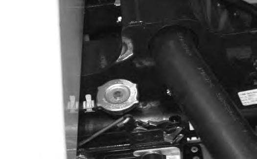
When the engine is cool, loosen and remove the radiator cap (Item 1) [Figure 296]
After all the coolant is removed, close both drain valves. Recycle or dispose of the used coolant in an environmentally safe manner.
Mix the coolant in a separate container. (See ENGINE COOLING SYSTEM on Page 163.) and (See Capacities on Page 220.)
NOTE: The cooling system is factory filled with propylene glycol (purple colour). DO NOT mix propylene glycol with ethylene glycol.
The correct mixture of coolant to provide a -37°C (-34°F) freeze protection is 5 L propylene glycol mixed with 4,4 L of water OR 1 U.S. gal propylene glycol mixed with 3.5 qt of water.
Add premixed coolant; 47% water and 53% propylene glycol to the recovery tank if the coolant level is low.
Use a refractometer to check the condition of propylene glycol in your cooling system.
Add premixed coolant until the level is correct.
Run the engine until it is at operating temperature. Stop the engine. Check the coolant level and add as needed. Be sure the radiator cap is tight.
Add coolant to the recovery tank as needed.
Close the tailgate.
Description
Figure 299
The excavator has a 12 volt, negative earth electrical system. The electrical system is protected by fuses (Item 1) [Figure 299] located under the right side cover of the excavator. The fuses will protect the electrical system when there is an electrical overload. The reason for the overload must be found and corrected before starting the engine again.
The battery cables must be clean and tight. Check the electrolyte level in the battery. Add distilled water as needed. Remove acid or corrosion from the battery and cables with a sodium bicarbonate and water solution.
Put Battery Saver P/N 6664458 or grease on the battery terminals and cable ends to prevent corrosion.
Warning
AVOID INJURY OR DEATH
Batteries contain acid which burns eyes and skin on contact. Wear goggles, protective clothing and rubber gloves to keep acid off body.
In case of acid contact, wash immediately with water. In case of eye contact get prompt medical attention and wash eye with clean, cool water for at least 15 minutes.
If electrolyte is taken internally drink large quantities of water or milk! DO NOT induce vomiting. Get prompt medical attention.
W-2065-0807
Fuse And Relay Location / Identification
A decal is inside the fuse cover to show location and amp ratings.
Remove the cover to check or replace the fuses and relays

The location and sizes are shown in [Figure 300]
Always replace fuses using the same type and capacity.
ELECTRICAL SYSTEM (CONT’D)
Fuse And Relay Location / Identification (Cont’d)
Figure 300
The location and sizes are shown in the table below and on the decal [Figure 300]. Relays are identified by the letter “R” in the AMP column.

ELECTRICAL SYSTEM (CONT’D)
Shut-Off Switch
Open the right side cover. (See RIGHT SIDE COVER on Page 152.)
Figure 301
The shut-off switch (Item 1) [Figure 301] is located under the right side cover below the fuse panel.
Rotate the switch (Item 1) [Figure 301] anticlockwise to turn the switch to the OFF position, clockwise to turn to the ON position.
Battery Maintenance
Open the right side cover. (See RIGHT SIDE COVER on Page 152.)
Figure 302
The battery (Item 1) [Figure 302] is located in the front of the right side upperstructure.
The battery cables must be clean and tight [Figure 303] Remove acid or corrosion from the battery and cables using a sodium bicarbonate and water solution. Cover the battery terminals and cable ends with battery saver grease to prevent corrosion.
Check for broken or loose connections.
If the battery cables are removed for any reason, disconnect the negative (-) cable first. When installing the battery cables, make the last connection the negative (-) cable to the battery.
The original equipment battery is maintenance free. If a replacement battery is installed, check the electrolyte level in the battery.

If the electrolyte level is lower than 13 mm (0.50 in) above the plates, add distilled water only.

Warning
AVOID INJURY OR DEATH
Batteries contain acid which burns eyes and skin on contact. Wear goggles, protective clothing and rubber gloves to keep acid off body.
In case of acid contact, wash immediately with water. In case of eye contact get prompt medical attention and wash eye with clean, cool water for at least 15 minutes.
If electrolyte is taken internally drink large quantities of water or milk! DO NOT induce vomiting. Get prompt medical attention. W-2065-0807
ELECTRICAL SYSTEM (CONT’D)
Using A Booster Battery (Jump Starting)
Important
If jump starting the excavator from a second machine:
When jump starting the excavator from a battery installed in a second machine, make sure the engine is NOT running while using the glow plugs. High voltage spikes from a running machine can burn out the glow plugs.
I-2060-0906
If it is necessary to use a booster battery to start the engine, BE CAREFUL! There must be one person in the operator’s seat and one person to connect and disconnect the battery cables.
Be sure the key switch is OFF. The booster battery must be 12 volt.
Open the tailgate. (See TAILGATE on Page 151.)
NOTE: (See Cold Temperature Starting on Page 73.)
Important
Damage to the alternator can occur if:

•Engine is operated with battery cables disconnected.
•Battery cables are connected when using a fast charger or when welding on the excavator. (Remove both cables from the battery.)
•Extra battery cables (booster cables) are connected wrong.
I-2223-0903
Warning
AVOID INJURY OR DEATH
Batteries contain acid which burns eyes and skin on contact. Wear goggles, protective clothing and rubber gloves to keep acid off body.
In case of acid contact, wash immediately with water. In case of eye contact get prompt medical attention and wash eye with clean, cool water for at least 15 minutes.
If electrolyte is taken internally drink large quantities of water or milk! DO NOT induce vomiting. Get prompt medical attention.
W-2065-0807
Connect one end of the first cable to the positive (+) ter minal of the booster battery. Connect the other end of the same cable to the positive (+) terminal (Item 1) [Figure 304] of the excavator starter.
Connect one end of the second cable to the negative (-) ter minal of the booster battery. Connect the other end of the same cable to the starter mounting bolt (Item 2) [Figure 304]
Start the engine. After the engine has started, remove the earth (-) cable first (Item 2) [Figure 304]
Disconnect the cable from the excavator starter (Item 1) [Figure 304].
ELECTRICAL SYSTEM (CONT’D)
Removing And Installing The Battery
Open the right side cover. (See RIGHT SIDE COVER on Page 152.)
Disconnect the negative (-) cable (Item 1) [Figure 305] first.
Disconnect the positive (+) cable (Item 2) [Figure 305]
Remove the bolt (Item 1) [Figure 306] and remove the hold-down clamp.
Remove the battery.
Always clean the terminals and the cable ends, even when installing a new battery.
Install the battery. Install the hold-down clamp and tighten the bolts.

Connect the battery cables. Connect the negative (-) cable (Item 1) [Figure 305] last to prevent sparks.
Warning
AVOID INJURY OR DEATH
Batteries contain acid which burns eyes and skin on contact. Wear goggles, protective clothing and rubber gloves to keep acid off body.
In case of acid contact, wash immediately with water. In case of eye contact get prompt medical attention and wash eye with clean, cool water for at least 15 minutes.
If electrolyte is taken internally drink large quantities of water or milk! DO NOT induce vomiting. Get prompt medical attention.
W-2065-0807
Hydraulic System
Checking And Adding Hydraulic Oil
Put the machine on a flat level surface.
Retract the arm and bucket cylinders, extend the boom cylinder, put the bucket on the ground and lower the blade. Stop the engine.
Open the right side cover. (See RIGHT SIDE COVER on Page 152.)
Figure 307
Park the machine in the position shown [Figure 307] (The preferred method is to check the hydraulic oil when it is cold.)

Check the hydraulic oil level, it must be visible in the sight gauge (Item 1) [Figure 307]. The decal on the hydraulic tank shows the correct fill level.
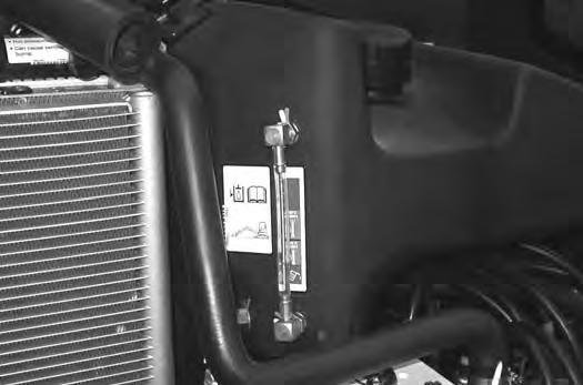
A - Correct Oil Level COLD (Preferred)
B - Correct Oil Level HOT (Optional)
Clean the surface around the reservoir cap and remove the cap from the reservoir (Item 2) [Figure 307].
Warning
Avoid Injury Or Death
Always clean up spilled fuel or oil. Keep heat, flames, sparks or lighted tobacco away from fuel and oil. Failure to use care around combustibles can cause explosion or fire.
W-2103-0508
Figure 308
Check the condition of the fill strainer screen (Item 1) [Figure 308]. Clean or replace as necessary.
Be sure the screen is installed before adding fluid. Add the correct fluid (See [Figure 309]) to the reservoir until it is visible in the sight gauge. (See Capacities on Page 220.)
Check the cap and clean as necessary. Replace the cap if damaged.
Install the cap.
Close the right side cover and tailgate.
Hydraulic / Hydrostatic Fluid Chart

Figure 309
HYDRAULIC / HYDROSTATIC FLUID RECOMMENDED ISO VISCOSITY GRADE (VG) AND VISCOSITY INDEX (VI)
TEMPERATURE RANGE ANTICIPATED DURING MACHINE USE
[1] VG 100; Minimum VI 130
[2] VG 46; Minimum VI 150
[3] BOBCAT All-Season Fluid
[4] BOBCAT Synthetic Fluid
[5] BOBCAT Biodegradable Hydraulic / Hydrostatic Fluid (Unlike biodegradable fluids that are vegetable based, Bobcat biodegradable fluid is formulated to prevent oxidation and thermal breakdown at operating temperatures.)
Use only recommended fluid in the hydraulic system [Figure 309].
HYDRAULIC SYSTEM (CONT’D)
Removing And Replacing The Hydraulic Filters
Warning
AVOID INJURY OR DEATH
Always clean up spilled fuel or oil. Keep heat, flames, sparks or lighted tobacco away from fuel and oil. Failure to use care around combustibles can cause explosion or fire.
W-2103-0508
Hydraulic Filter
See the SERVICE SCHEDULE for the correct service interval. (See SERVICE SCHEDULE on Page 145.)
Remove the hydraulic filter (Item 1) [Figure 311]
Clean the housing where the filter gasket makes contact. Put clean hydraulic fluid on the gasket. Install the new filter and hand tighten only. Use a genuine Bobcat replacement filter.

Open the right side cover. (See RIGHT SIDE COVER on Page 152.)
For easier access to change the hydraulic filter, remove the lower right side panel.
Remove the four bolts (Item 1) from the side panel (Item 2) [Figure 310]. Remove the side panel.
HYDRAULIC SYSTEM (CONT’D)
Removing And Replacing The Hydraulic Filters (Cont’d)
Warning
AVOID INJURY OR DEATH
Always clean up spilled fuel or oil. Keep heat, flames, sparks or lighted tobacco away from fuel and oil. Failure to use care around combustibles can cause explosion or fire.
W-2103-0508
Case Drain Filter
See the SERVICE SCHEDULE for the correct service interval. (See SERVICE SCHEDULE on Page 145.)
The case drain filter is located in the right front corner of the excavator.
Open the right side cover. (See RIGHT SIDE COVER on Page 152.)
For easier access to change the case drain filter, remove the lower right side panel.
Remove the four bolts (Item 1) from the side panel (Item 2) [Figure 310]. Remove the side panel.
P-97141
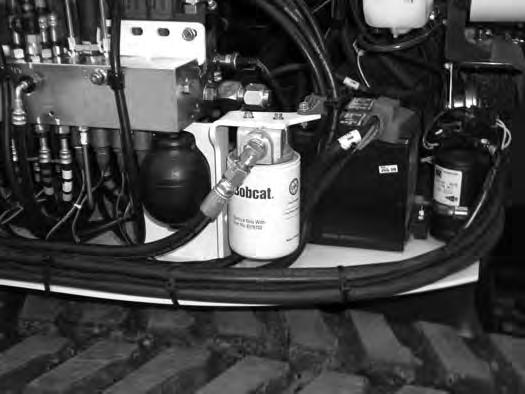
Remove the case drain filter (Item 1) [Figure 312].
Clean the housing where the filter gasket makes contact.
Put clean hydraulic fluid on the gasket. Install the new filter and hand tighten only.
HYDRAULIC SYSTEM (CONT’D)
Removing And Replacing The Hydraulic Fluid

See the SERVICE SCHEDULE for the correct service interval. (See SERVICE SCHEDULE on Page 145.)
Warning
Avoid Injury Or Death
Diesel fuel or hydraulic fluid under pressure can penetrate skin or eyes, causing serious injury or death. Fluid leaks under pressure may not be visible. Use a piece of cardboard or wood to find leaks. Do not use your bare hand. Wear safety goggles. If fluid enters skin or eyes, get immediate medical attention from a doctor familiar with this injury.
W-2072-EN-0909
Retract the arm and bucket cylinders, lower the bucket to the ground. Stop the engine.
Open the tailgate. (See TAILGATE on Page 151.)
Reposition the drain hose out the bottom of the upperstructure and remove the cap (Item 1) [Figure 314]
Drain the fluid into a container.
Recycle or dispose of the fluid in an environmentally safe manner.
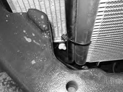
Install the cap (Item 1) [Figure 314] and position the drain hose back to the storage position (Item 1) [Figure 313]
Add fluid to the reservoir. (See HYDRAULIC SYSTEM on Page 171.)
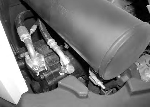
The hydraulic oil drain hose (Item 1) [Figure 313] is located below the oil cooler in the right rear corner of the upperstructure.
With the engine OFF, loosen the hose (Item 1) [Figure 315] on the hydraulic pump until all air is purge from the system. Tighten the hose after a steady stream of hydraulic fluid, free of any air bubbles, drains from the hose. DO NOT RUN THE MACHINE WITH THE HOSE LOOSE.
Start the engine and operate the machine through the hydraulic functions. Stop the engine. Check the fluid level and add as needed.

Spark Arrester Muffler
Cleaning Procedure
See the SERVICE SCHEDULE for the correct service interval. (See SERVICE SCHEDULE on Page 145.)
Warning
Avoid Injury Or Death
When an engine is running in an enclosed area, fresh air must be added to avoid concentration of exhaust fumes. If the engine is stationary, vent the exhaust outside. Exhaust fumes contain odorless, invisible gases which can kill without warning.
W-2050-0807
Warning
Stop engine and allow the muffler to cool before cleaning the spark chamber. Wear safety goggles. Failure to obey can cause serious injury.
W-2011-1285
Warning
Never use machine in atmosphere with explosive dust or gases or where exhaust can contact flammable material. Failure to obey warnings can cause injury or death.
W-2068-1285
Warning
When the engine is running during service, the steering levers must be in neutral.
Failure to do so can cause injury or death.
W-2203-0595
Do not operate the excavator with a defective exhaust system.
Stop the engine. Open the tailgate. (See TAILGATE on Page 151.)
Remove the plug (Item 1) [Figure 316] from the bottom of the muffler.
Start the engine and run for about 10 seconds while a second person, wearing safety glasses, holds a piece of wood over the outlet of the muffler. The carbon deposits will be forced out of the muffler plug hole (Item 1) [Figure 316]

Stop the engine. Install and tighten the plug.
Close the tailgate.
Important
This machine is factory equipped with a spark arrester exhaust system.
The spark arrester muffler, if equipped, must be cleaned to keep it in working condition. The spark arrester muffler must be serviced by dumping the spark chamber every 100 hours of operation.
On some models, the turbocharger functions as the spark arrester and must operate correctly for proper spark arrester function.
If this machine is operated on flammable forest, brush, or grass covered land, a spark arrester attached to the exhaust system may be required and must be maintained in working order. Refer to local laws and regulations for spark arrester requirements.
I-2284-EN-0909
Track Tension
NOTE: The wear of the pins and bushings on the undercarriage vary with the working conditions and the different types of soil conditions. It is necessary to inspect track tension and maintain the correct tension. See SERVICE SCHEDULE for the correct service interval. (See SERVICE SCHEDULE on Page 145.)
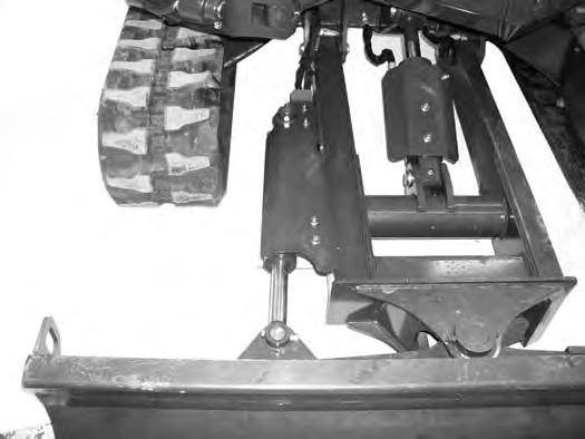
Raise one side of the machine (Approximately four inches) using the boom and arm.
Raise the blade fully and install jackstands under the blade and track frame (Item 1) [Figure 317]. Lower the boom until all machine weight is on the jackstands.
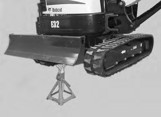
Stop the engine.
Warning
AVOID INJURY
Keep fingers and hands out of pinch points when checking the track tension.
TRACK TENSION (CONT’D)
Adjusting (Cont’d)
Rubber Track Clearance
Figure 318
10 - 15 mm
- 0.59 in)
Steel Track Clearance
Figure 320
- 0.59 in)
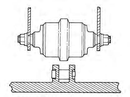
Measure the clearance at the middle track roller. Do not get fingers into pinch points between the track and the track roller. Use a bolt or a dowel of the appropriate size to check the gap between the contact edge of the roller and the top edge of the track guide [Figure 318] and [Figure 319]
Rubber Track Clearance - 10 - 15 mm (0.39 - 0.59 in).
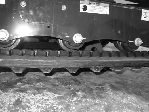
Measure the track clearance at the middle track roller. Do not get fingers into pinch points between the track and the track roller. Us a bolt or dowel of the appropriate size to check the gap between the contact edge of the roller and the top edge of the track guide [Figure 320]
Steel Track Clearance - 17,3 - 30 mm (0.68 - 1.18 in).
TRACK TENSION (CONT’D)
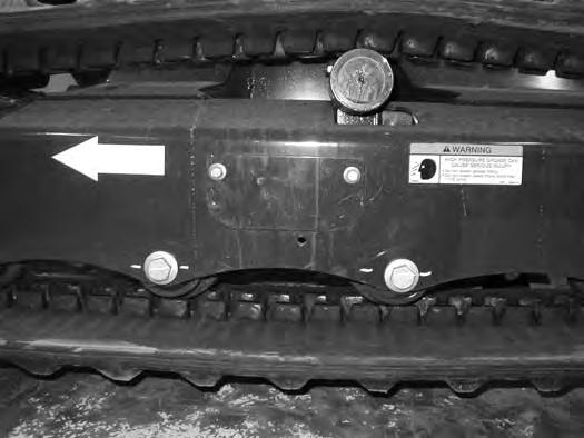
Adjusting (Cont’d)
Warning
HIGH PRESSURE GREASE CAN CAUSE SERIOUS INJURY •Do not loosen the track tension fitting more than 1 - 1/2 turns.


W-2994-0515
With Bleed Screw and Track Tension Fitting
Figure 322
Add grease to the track tension fitting (Item 1) [Figure 322] until the track tension is correct.
With One Piece - Track Tension Fitting
Figure 324
The tension removal tool (P/N 6675936) is available and recommended to direct the flow of grease to aid in cleanup. Always dispose of the grease in an environmentally friendly manor.
Use tool 6675936 (Item 1) [Figure 323] to loosen the bleed fitting (Item 2) [Figure 322] to release tension from the track. Do not loosen the bleed fitting more than 1-1/2 turns.
The tool is sized to fit the bleed fitting (Item 2) [Figure 322]
NOTE: Do not loosen the track tension fitting (Item 1) [Figure 322].
Repeat the procedure for the opposite side.
Add grease to the track tension fitting (Item 1) [Figure 324] until the track tension is correct.
Figure 325
The tension removal tool (P/N 7277225) is available and recommended to direct the flow of grease to aid in cleanup. Always dispose of the grease in an environmentally friendly manor.
Use tool 7277225 (Item 1) [Figure 325] to loosen the track tension fitting (Item 1) [Figure 324] to release tension from the track.
The tool is sized to fit the one piece track tension fitting (Item 1) [Figure 324]
NOTE: Do not loosen the track tension fitting (Item 1) [Figure 324] more than 1-1/2 turns.
Installation: Tighten the track tension fitting to 24 - 30 N•m (18 - 22 ft-lb) torque.
Repeat the procedure for the opposite side.
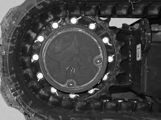
Travel Motor
Checking And Adding Oil
Figure 326
Park the excavator on a level surface with the plugs (Items 1 and 2) [Figure 326] positioned as shown.
Remove the plug (Item 1) [Figure 326]. The lube level must be at the bottom edge of the hole.
Add lubricant (SAE 90W) through the hole (Item 1) [Figure 326] if the lube level is low.
Repeat the procedure for the opposite travel motor.
Removing And Replacing Oil
See the SERVICE SCHEDULE for the correct service interval. (See SERVICE SCHEDULE on Page 145.)
Warning
Avoid Injury Or Death
Always clean up spilled fuel or oil. Keep heat, flames, sparks or lighted tobacco away from fuel and oil. Failure to use care around combustibles can cause explosion or fire.
Park the excavator on a level surface with plugs (Items 1 and 2) [Figure 326] positioned as shown. Remove both plugs and drain the lubricant into a container.
Install the bottom plug (Item 2). Add lubricant (SAE 90W) through the plug hole (Item 1) [Figure 326] until the lube level is at the bottom edge of the hole. (See Capacities on Page 220.)
Install the plug (Item 1) [Figure 326]
Repeat the procedure for the opposite travel motor.
Alternator Belt
Belt Adjustment
The alternator belt is a special maintenance free type that is pretensioned over the pulleys. This belt eliminates the need for a tensioning device and does not require periodic adjustment. Contact your Bobcat dealer for replacement parts.
Belt Replacement
Stop the engine and open the tailgate. (See TAILGATE on Page 151.)
NOTE:If the machine is equipped with air conditioning, the compressor belt will need to be removed before the alternator belt can be removed.
The engine will need to be rotated by hand to remove the belt. To access the flywheel, remove the plug (Item 1) [Figure 328] from the flywheel housing. (A pry bar will be needed to rotate the flywheel to assist in belt removal and installation.)
Remove the air conditioning compressor belt (if equipped). (See AIR CONDITIONING COMPRESSOR BELT on Page 182.)
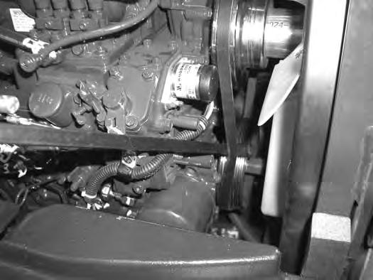
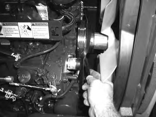
Remove the three bolts (Item 1) and remove the fan guard (Item 2) [Figure 327]
Use a pry bar between the belt and the crankshaft pulley (Item 1) [Figure 329]
Using a pry bar on the flywheel, rotate the engine by hand to push the belt off the crankshaft pulley. Continue to rotate the flywheel until the belt is loose.
ALTERNATOR BELT (CONT’D)
Belt Replacement (Cont’d)
Installation
Position the
Install
Use a
Using a pry bar, rotate the flywheel by hand while using the second pry bar to install the belt over the fan pulley.
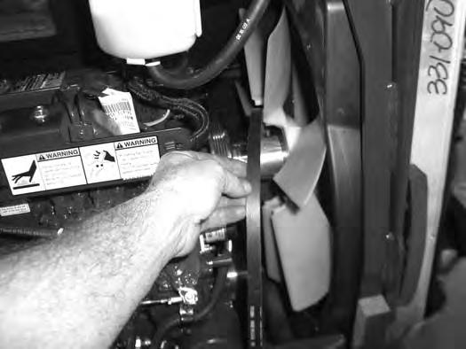
Continue to rotate the engine by hand until the belt is fully on the pulleys.
Reinstall the rubber plug (Item 1) [Figure 328]
Install the fan guard (Item 2) with the three bolts (Item1) [Figure 327]
Close the tailgate.
Air Conditioning Compressor Belt
Belt Adjustment
The compressor belt is a special maintenance free type that is pretensioned over the pulleys. This belt eliminates the need for a tensioning device and does not require periodic adjustment. Contact your Bobcat dealer for replacement parts.
Belt Replacement
Stop the engine and open the tailgate. (See TAILGATE on Page 151.)
The engine will need to be rotated by hand to remove the belt. To access the flywheel, remove the plug (Item 1) [Figure 332] from the flywheel housing.
Use a pry bar (Item 1) [Figure 333] to push the belt off of the pulley. Using a pry bar on the flywheel, rotate the engine by hand to push the belt off the crankshaft pulley. Continue to rotate the flywheel until the belt is loose. Remove the belt.
Position the belt (Item 1) [Figure 334] over the crankshaft pulley and to the compressor pulley.
Use a pry bar (Item 2) [Figure 334] to position the belt on the pulley while using the second pry bar at the flywheel to rotate the engine by hand.
Continue to rotate the engine by hand until the belt is fully on the pulleys.


Reinstall the rubber plug (Item 1) [Figure 332].
Close the tailgate.
Track Roller And Idler Lubrication
Procedure
The track rollers and idlers require no maintenance. The bearings are a sealed design.
QUICK COUPLER
Quick Coupler And Attachment Inspection And Maintenance
Figure 335
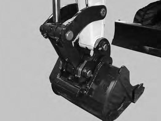
Inspect the quick coupler for wear or damage. Inspect the quick coupler pins (Item 1) and the hooks (Item 2) [Figure 335] (on the attachment) for wear or damage

Repair or replace damaged parts.
X-CHANGE

Inspection And Maintenance
Figure 336
Inspect the X-Change for wear or damage. Inspect the XChange pins (Item 1) and hooks (Item 2) [Figure 336] (on the attachment) for wear or damage.
Repair or replace damaged parts.
PIN GRABBER QUICK COUPLER
Inspection And Maintenance
Figure 337
Inspect the pin grabber clasps (Item 1) and the pins (Item 2) [Figure 337] (on the attachment) for wear or damage.

Repair or replace damaged parts.
Pin Grabber Quick Coupler Troubleshooting
If the Pin Grabber Quick Coupler does not function correctly, the following components may need servicing. See your Bobcat dealer for service.
Bucket Teeth Removal And Installation
Warning
Wear safety glasses to prevent eye injury when any of the following conditions exist:
•Pressurised fluids and springs or other stored energy components.
•Flying debris or loose material is present.
•Engine is running.
•Tools are being used.
W-2505-EN-1009
Position the bucket so the bucket teeth are at a 30° angle up from the ground for accessibility to the teeth.
Lower the boom until the bucket is fully on the ground.
Stop the engine and exit the excavator.
The retaining pin (Item 1) must be installed as shown [notch (Item 2) to the front] for proper fit and tooth retention. The side of the tooth point (Item 3) [Figure 338] also shows the correct orientation of the retaining pin.
Installation: Position the new tooth point on the shank and install a new retaining pin. Install the retaining pin until it is flush with the top of the point.

LUBRICATION OF THE HYDRAULIC EXCAVATOR
Lubrication Locations
Lubricate the excavator as specified in the SERVICE SCHEDULE for the best performance of the machine. (See SERVICE SCHEDULE on Page 145.)
Always use a good quality lithium based multipurpose grease when lubricating the machine. Apply the lubricant until extra grease shows.

NOTE:Use Extra Heavy Gear Shield grease for grease fittings (Item 20, 21 and 22).
Lubricate the following locations on the excavator EVERY 8 - 10 HOURS:
LUBRICATION OF THE HYDRAULIC EXCAVATOR (CONT’D)


Lubrication Locations (Cont’d)

LUBRICATION OF THE HYDRAULIC EXCAVATOR (CONT’D)
Lubrication Locations (Cont’d)
Figure 346
15.Bucket Cylinder Rod End (1) [Figure 346]
16.Bucket Link Pin (1) [Figure 346]
17.Bucket Pivot (3) [Figure 346]
18.Bucket Link - without extendable arm (2), with extendable arm (4) [Figure 346]
19.Arm (1) [Figure 346]
Figure 347
Lubricate the following locations on the hydraulic excavator EVERY 50 HOURS:
NOTE:Use Extra Heavy Gear Shield grease for grease fittings (Item 20, 21 and 22).
20.Swing Circle (1) [Figure 347]
21.Swing Pinion (1) [Figure 347]. (Install 3 to 4 pumps of grease then rotate the upperstructure 90°. Install 3 to 4 pumps of grease and again rotate the upperstructure 90°. Repeat this until the slew pinion has been greased at four positions.)
Lubricate the following location on the hydraulic excavator EVERY 1000 HOURS:
NOTE:Use Extra Heavy Gear Shield grease for grease fittings (Item 20, 21 and 22).

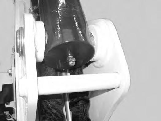
22.Boom Swing Cylinder Base (1) [Figure 348]
NOTE:The boom swing grease fitting is located on the side of base end of the cylinder.

The pivots and cylinders (Item 1) have a large pin held in position with a bolt (Item 2) and double nuts (Item 3) [Figure 349] securing the pin.
The two nuts (Item 3) are used as jam nuts to hold the bolt (Item 2) with out tightening the bolt (Item 2) to the pin boss. After the nuts (Item 3) are tightened together, the bolt (Item 2) should be free to spin. See your Bobcat dealer for replacement parts.
EXCAVATOR STORAGE AND RETURN TO SERVICE Storage
Sometimes it may be necessary to store your Bobcat Excavator for an extend period of time. Below is a list of items to perform before storage.
•Thoroughly clean the excavator including the engine compartment.
•Lubricate the excavator.
•Replace worn or damaged parts.
•Drive the excavator onto planks in a dry protected shelter.
•Lower the boom fully with the bucket flat on the ground.
•Put grease on any exposed cylinder rods.
•Put fuel stabiliser in the fuel tank and run the engine a few minutes to circulate the stabiliser to the pump and fuel injectors.
•Drain and flush the cooling system. Refill with premixed coolant.
•Replace all fluids and filters (engine, hydraulic).
•Replace all filters (i.e.: air cleaner, heater, etc.).
•Put all controls in NEUTRAL position.
•Remove the battery. Be sure the electrolyte level is correct then charge the battery. Store it in a cool dry place above freezing temperatures and charge it periodically during storage.
•Cover the exhaust pipe opening.
•Tag the machine to indicate that it is in storage condition.
Return To Service
After the Bobcat Excavator has been in storage, it is necessar y to follow a list of items to return the excavator to service.
•Check the engine and hydraulic oil levels; check coolant level.
• Install a fully charged battery.
•Remove grease from exposed cylinder rods.
•Check all belt tensions.
•Be sure all shields and guards are in place.
•Lubricate the excavator.
•Remove cover from exhaust pipe opening.
•Start the engine and let run for a few minutes while observing the instrument panels and systems for correct operation.
•Drive the excavator off of the planks.
•Operate machine, check for correct function.
•Stop the engine and check for leaks. Repair as needed.
Diagnostic Service Codes
Viewing Service Codes
The Service Codes will aid your dealer in diagnosing conditions that can damage your machine.
Standard Instrument Panel

Figure 350
Press the Information button (Item 2) to cycle the data display (Item 1) [Figure 350] until the service code screen is displayed. If more than one service code is present, the codes will scroll on the data display.
When no service code is present, [NONE] is displayed [Figure 350].
NOTE:Corroded or loose earths can cause multiple service codes and / or abnormal symptoms. All instrument panel lights flashing, alarm sounding, headlights and taillights flashing, can indicate a bad earth. The same symptoms can apply if the voltage is low, such as loose or corroded battery cables. If you observe these symptoms, check earths and positive leads first.
Deluxe Instrument Panel
The last 40 codes stored in history can also be viewed using the Deluxe Instrument Panel.
Press a scroll button (Item 1) repeatedly until the Active Warnings screen icon (Inset) is highlighted.
The ACTIVE WARNINGS screen displays active service codes. Press [9] to view the next service code if more than one is present. Press [4] to display a history of service codes.
The WARNINGS HISTORY screen will list the Service Code Number (CODE), Hourmeter reading when the error occurred (HOUR), and the User (USER) who was logged in to operate the machine when the error occurred.
Press [9] to view the next eight service codes.
A total of 40 codes can be stored. When more than 40 codes occur, the oldest code will disappear and the newest code will be in the number 1 position.
Press the list number next to the service code for more detail.
Press the left scroll button to back up one screen.
DIAGNOSTIC SERVICE CODES (CONT'D)
Number Codes List
CODE
E0105Throttle actuator short to battery
E0106Throttle actuator short to earth
E0107Throttle actuator open circuit
E0123Throttle actuator not calibrated
E03215 volt supply out of range high
E03225 volt supply out of range low
E0421Throttle sensor out of range high
E0422Throttle sensor out of range low
E0521Throttle actuator feedback out of range high
E0522Throttle actuator feedback out of range low
E3128Interrupted power failure log only
E3297Controller programmed log only
CODE
L0102Lights Button Error On
L0202High Flow Button Error On
L0302Auxiliary Button Error On
L0402Information Button Error On
L7404Gateway Controller No Communication
L7672Left Hand Panel Programming Error
M0216Hydraulic Filter Not Connected
M0217Hydraulic Filter Plugged
M0309Battery Voltage Low
M0310Battery Voltage High
M0311Battery Voltage Extremely High
M0314Battery Voltage Extremely Low
M0322Battery Voltage Out of Range Low
M0414Engine Oil Pressure Extremely Low
M0415Engine Oil Pressure Shutdown
H2521Angle Blade Control Switch Out of Range High
H2522Angle Blade Control Switch Out of Range Low
DIAGNOSTICS SERVICE CODE (CONT’D)
Number Codes List (Cont’d) CODE CODE
M0909Fuel Level Low M2721Throttle Sensor Out of Range High
M0921Fuel Level Out of Range High
M0922Fuel Level Out of Range Low
M1121Console Sensor Out of Range High
M1122Console Sensor Out of Range Low
M1128Console Sensor Failure
M1305Fuel Hold Solenoid Short to Battery
M1306Fuel Hold Solenoid Short to Earth
M1307Fuel Hold Solenoid Open Circuit
M2722Throttle Sensor Out of Range Low
M3128Interrupted Power Failure
M3204 Throttle Controller No Communication
M3304Deluxe Panel No Communication
M3404RFID Key Controller No Communication
M3702Hyd Exchange Output Error On
M1402Fuel Pull Output Error On M3703Hyd Exchange Output Error Off
M1403Fuel Pull Output Error Off
M1407Fuel Pull Output Open Circuit
M1428Fuel Pull Output Failure
M4109Alternator Low
M1705Hydraulics Enable Solenoid Short to Battery M4110Alternator High
M1706Hydraulics Enable Solenoid Short to Earth
M1707Hydraulics Enable Solenoid Open Circuit
M1732Hydraulics Enable Solenoid Overcurrent
M2005Two-Speed Solenoid Short to Battery M2006Two-Speed to Earth
M4304Keyless Start Panel No Communication
M4404Secondary Controller No
Output Open Circuit M5206Offset Base Solenoid Short to Earth
M2228Starter Output Failure M5207Offset Base Solenoid Open Circuit M5232Offset Base Solenoid Overcurrent
M2302Starter Relay Error On M2303Starter Relay Error Off M5305Offset Rod Solenoid Error On
M5306Offset Rod Solenoid Short to Earth
M2402Fuel Pull Relay Error On M5307Offset Rod Solenoid Open Circuit
M2403Fuel Pull Relay Error Off M5332Offset Rod Solenoid Overcurrent
M2521Load Sense Sensor Out of Range High
M2522Load Sense Sensor Out of Range Low
M2602Glow Plug Relay Error On
M2603Glow Plug Relay Error Off
M5421Offset Control Switch Out of Range High
M5422Offset Control Switch Out of Range Low
M5424Offset Control Switch Out of NEUTRAL
DIAGNOSTICS SERVICE CODE (CONT’D)
Number Codes List (Cont’d)
CODE
M5505Auxiliary Base Solenoid Short to Battery
M5506Auxiliary Base Solenoid Short to Earth
M5507Auxiliary Base Solenoid Open Circuit
M5532Auxiliary Base Solenoid Overcurrent
M5605Auxiliary Rod Solenoid Short to Battery
M5606Auxiliary Rod Solenoid Short to Earth
M5607Auxiliary Rod Solenoid Open Circuit
M5632Auxiliary Rod Solenoid Overcurrent
M5721Auxiliary Control Switch Out of Range High
M5722Auxiliary Control Switch Out of Range Low
M5724Auxiliary Control Switch Out of NEUTRAL
M6204Load Moment Sensor In Error
M6402Switched Power Relay Error On
M6403Switched Power Relay Error Off
M6702HVAC Output Error On
M6703HVAC Output Error Off
M6905Hydraulic Throttle Solenoid Short to Battery
M6906Hydraulic Throttle Solenoid Short to Battery
M6907Hydraulic Throttle Solenoid Open Circuit
M6923Hydraulic Throttle Solenoid Not Calibrated
M6932Hydraulic Throttle Solenoid Overcurrent
M7002Switched Power Output Error On
M7003Switched Power Output Error Off
M7007Switched Power Output Open Circuit
M7028Switched Power Output Failure
CODE
M7423Main Controller Not Programmed
M7497Main Controller Software Updated
M7604Standard Display Panel No Communication
M7748Key Switch Multiple
M7839Hourmeter Changed
R7404No Communication To Main Controller
CONTROL PANEL SETUP
Panel Setup (Deluxe Instrument Panel)
Icon Identification
Figure 351
ICON DESCRIPTION
DATE / TIME
USER / USER HOURS
MACHINE HOURS (HOURMETER)
ACTIVE WARNINGS screen icon
VITALS screen icon
SERVICE screen icon
AUTO IDLE Status icon
ATTACHMENTS screen icon
MACHINE SETTINGS screen icon
DISPLAY screen icon
HOME icon (Return to MAIN screen)
LEFT SCROLL button
RIGHT SCROLL button
ENTER button
Vitals
Press a scroll button (Item 1) repeatedly until the Vitals screen icon (Inset) is highlighted.
Displays select system operating levels.
You can monitor real-time displays of:
Engine Speed (RPM)
Engine Coolant Temperature
System Voltage
Hydraulic Fluid Temperature
The Deluxe Instrument Panel is easy to use. Continue to set your own preferences for operating / monitoring your Bobcat excavator.

CONTROL PANEL SETUP (CONT’D)
Panel Setup (Deluxe Instrument Panel) (Cont’d)


Date And TimeLanguages
Press a scroll button (Item 1) repeatedly until the Display screen icon (Inset) is highlighted.
Select [1. CLOCKS].
Select [1. TIME]
Use the keypad to enter time.
Select AM / PM / 24hr.
Press [ENTER] to continue.
Select [2. DATE]
Use the keypad to enter date.
Press [ENTER] to continue.
Press a scroll button (Item 1) repeatedly until the Display screen icon (Inset) is highlighted.
Select [2. LANGUAGES]
Select the desired language.
Press a scroll button (Item 1) repeatedly until the Display screen icon (Inset) is highlighted.
Select [4.
Press [1] to cycle between ENGLISH and METRIC.
CONTROL PANEL SETUP (CONT’D)
Panel Setup (Deluxe Instrument Panel) (Cont’d)
Auto Idle Time DelayJob Clock Reset
Press a scroll button (Item 1) repeatedly until the Security screen icon (Inset) is highlighted.
Select [3. MACHINE PERFORMANCE]
Select [1. AUTO IDLE DELAY TIME]
Use the keypad to enter the desired delay time between 4 and 250 seconds.


Press [ENTER] to save and continue. Press left scroll button to exit without saving.
Press a scroll button (Item 1) repeatedly until the Security screen icon (Inset) is highlighted.
Select [1. PASSWORDS / LOCKOUTS]
Enter owner password and press [ENTER].
Select [1. USER SETTINGS].
Select user.
Press [9] to reset job statistics.
Press left scroll button or [0] to exit without saving.
CONTROL PANEL SETUP (CONT’D)
Panel Setup (Deluxe Instrument Panel) (Cont’d)
Press a scroll button (Item 1) repeatedly until the Display screen icon (Inset) is highlighted.
Select [3. ALARM CLOCK].
Select [1. OFF ONCE], Select [2. ON Daily] or Select [3. ON WEEKLY]
Select [1. OFF / ON], Select [2. TIME] or Select [3. DAILY]
Use key pad numbers to set time.
Select [7. AM], Select [8. PM] or Select [9. 24 hr clock].
Select [ENTER] to save. Press left scroll to back space numbers.
Press [4] to set alarm to sleep. (When pressed, display will return to main screen.)
Press [9] to shut off alarm. Alarm will still be active for the next day alarm setting. (When pressed, display will return to main screen.)
Press a scroll button (Item 1) repeatedly until the Security screen icon (Inset) is highlighted.
Select [3. MACHINE PERFORMANCE]
Select [2. ECO MODE]
ECO Mode will set the maximum engine rpm to be at 85% of the high idle setting.
Example: If the machine maximum engine speed is 2450 rpm, when ECO Mode is enabled, the maximum engine speed will be approximately 2080 rpm.

CONTROL PANEL SETUP (CONT’D)
Panel Setup (Deluxe Instrument Panel) (Cont’d)


Press a scroll button (Item 1) repeatedly until the Security screen icon (Inset) is highlighted.
1
Press a scroll button (Item 1) repeatedly until the Security screen icon (Inset) is highlighted.
MACHINE SETTINGS is visible on screen.
Select [2. MACHINE HISTORY]
Select [1. LOG-IN INFORMATION].
View User Log hours and last time / dated used.
Individual information can be viewed and reset back to zero
Select user [KEY PAD 19] to access individual user.
MACHINE SETTINGS is visible on screen.
Select [2. MACHINE HISTORY]
Select [2. USER JOB STATISTICS].
View Job Statistics (Job Hours / Idle Time
Information can be viewed and reset back to zero
PASSWORD SETUP (KEYLESS START PANEL)

Panel Setup (Deluxe Instrument Panel) (Cont’d)
Machine History - Overall Job StatisticsAttachments
Press a scroll button (Item 1) repeatedly until the Security screen icon (Inset) is highlighted.
MACHINE SETTINGS is visible on screen.
Select [2. MACHINE HISTORY]
Select [3. OVERALL JOB STATISTICS].
Press a scroll button (Item 1) repeatedly until the Attachment screen icon (Inset) is highlighted.
ATTACHMENTS is visible on screen.
Press [ENTER]
Press [4] or [9] repeatedly until the desired Attachment is visible in the display screen.
Information about the attachment, recommended auxiliary hydraulic flow and Tips about attachment operation will be displayed.
PASSWORD SETUP (KEYLESS START PANEL) (CONT’D)
Password Description
Master Password:
A permanent, randomly selected password set at the factory that cannot be changed. This password is used for service by the Bobcat dealer if the owner password is not known or to change the owner password.
Owner Password:
Allows for full use of the excavator. Must be used to change the owner password.
Changing The Owner Password
Turn the start switch (Item 1) [Figure 352] to the ON position to turn on the excavators electrical system.
Enter the five digit owner password using the number keys (1 through 0) if locked.
Password Lockout Feature
This feature allows the owner to unlock the password feature so that a password does not need to be used every time the engine is started.
Turn the start switch (Item 1) [Figure 353] to the ON position to turn on the excavators electrical system.
Enter the five digit owner password using the number keys (1 through 0).
Press and hold the lock (Item 2) and unlock (Item 3) [Figure 352] keys for 2 seconds.
The lock key red light will flash and the instrument panel display screen will show [ENTER]
Enter a new five digit owner password using the number keys (1 through 0). An asterisk will show in the left panel display screen for each key press.

The instrument panel display screen will show [AGAIN]
Enter the new five digit owner password again.
The lock key red light will become solid.
Press the unlock key (Item 2) [Figure 353]
The left panel display screen will show [CODE]
Enter the five digit owner password using the number keys (1 through 0). The unlock key green light will flash, then become solid.
The excavator can now be started without using a password.
NOTE:Use the following procedure to reset the machine lock so that the excavator requires a password to start the engine.
Turn the key switch to the ON position to turn on the excavators electrical system.
Press the lock key (Item 3) [Figure 353]
The lock key red light will flash and the left panel display screen will show [CODE]
Enter the five digit owner password using the number keys (1 through 0). The unlock key green light will flash, then the lock key red light will become solid.
You must now enter the password every time to start the excavator.
PASSWORD SETUP (DELUXE INSTRUMENT PANEL)
Password Setup is available on machines with a Deluxe Instrument Panel.
Password Description
All new machines with a Deluxe Instrument Panel arrive at Bobcat dealerships with the keypad in locked mode. Locked mode means that a password must be used to start the engine.
For security purposes, your dealer may change the password and set the keypad in the locked mode. Your dealer will provide you with the password.
Master Password:
A permanent, randomly selected password set at the factory that cannot be changed. This password is used for service by the Bobcat dealer if the owner password is not known or to change the owner password.
Owner Password:
Allows for full use of the excavator and to set up the Deluxe Instrument Panel. There is only one owner password. The owner password must be used to change the owner or user passwords. Owner should change the password as soon as possible for security of the excavator.
User Password:
Allows starting and operating the excavator; cannot change password or any of the other setup features.
For the procedures to change passwords: (See Changing The Owner Password on Page 204.) and (See Changing The User Passwords on Page 205.)
Changing The Owner Password
Press a scroll button (Item 1) repeatedly until the Security screen icon (Inset) is highlighted.
Select [1. PASSWORDS / LOCKOUTS]
Enter owner password and press [ENTER]
Select [1. USER SETTINGS].
Select [1. OWNER]
Select [2. CHANGE PASSWORD].
Enter new owner password and press [ENTER]
You will be prompted to reenter the new owner password.
PASSWORD SETUP (DELUXE INSTRUMENT PANEL) (CONT’D)
Press a scroll button (Item 1) repeatedly until the Security screen icon (Inset) is highlighted.
Select [1. PASSWORDS / LOCKOUTS]
This feature allows the owner to unlock the password feature so that a password does not need to be used every time the engine is started.
Press a scroll button (Item 1) repeatedly until the Security screen icon (Inset) is highlighted.
Select [1. PASSWORDS / LOCKOUTS].
Enter owner password and press [ENTER]
Enter owner password and press [ENTER].
Select [1. USER SETTINGS]
Select [2. MACHINE LOCK].
Select user.
Select [2. CHANGE PASSWORD]
NOTE:The procedure above can be followed to reset the machine lock so that the machine requires a password to start the engine.
NOTE:When the password is in UNLOCKED, no password is needed. The start switch is used to start the machine.
Enter new user password and press [ENTER]
Maintenance Clock
Description
The Maintenance Clock alerts the operator when the next ser vice interval is due. EXAMPLE: The maintenance clock can be set to a 500 hour interval as a reminder for the next 500 hour planned maintenance.
Standard Instrument Panel
Figure 354
During machine operation, a 2 beep alar m will sound when there are less than 10 hours until the next planned maintenance.
The remaining hours before maintenance is required (Item 1) will appear in the data display for 5 seconds while the service icon (Item 3) and the hourmeter icon (Item 2) [Figure 354] flash.
NOTE:The display will show negative numbers after counting down to zero.

The display will revert to the previous display and will appear for 5 seconds every time the machine is started until the maintenance clock is reset.
Setup
See your Bobcat dealer about installation of this feature.
Reset
Figure 355
Press the Information button (Item 2) [Figure 355] until the display screen shows the maintenance clock.
Press and hold the Information button (Item 2) for 7 seconds until [RESET] (Item 1) [Figure 355] appears in the display screen.
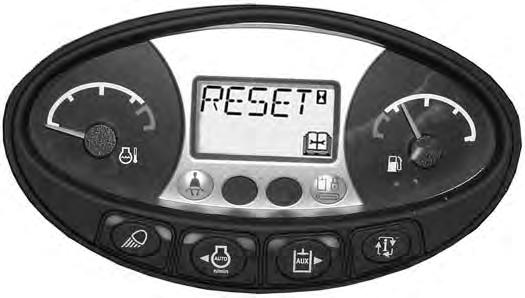
MAINTENANCE CLOCK (CONT’D)
Deluxe Instrument Panel
The Deluxe Instrument Panel (if equipped) will display a message (Item 1) [Figure 356] alerting the operator to service the machine.

This message will remain for 10 seconds and will appear for 10 seconds every time the machine is started until the maintenance clock is reset.

The Deluxe Instrument Panel (if equipped) will display a bar (Item 1) [Figure 357] showing the time remaining until next service. This bar will tur n red when service is past due. NEXT MAINTENANCE DUE will change to MAINTENANCE PAST DUE and display the number of hours past due.
Keys [4] and [9] can be used to adjust the service interval when the owner is logged in [Figure 357]